High-Speed Counter Module (Catalog Number 1746-HSCE) User Manual
Important User Information Solid state equipment has operational characteristics differing from those of electromechanical equipment. Safety Guidelines for the Application, Installation and Maintenance of Solid State Controls (Publication SGI-1.1 available from your local Rockwell Automation sales office or online at http://www.rockwellautomation.com/literature) describes some important differences between solid state equipment and hard-wired electromechanical devices.
Summary of Changes The information below summarizes the changes to this manual since the last printing. To help you find new and updated information in this release of the manual, we have included change bars as shown to the right of this paragraph. New Information Obsolete Information The table below lists sections that document new features and additional information about existing features, and shows where to find this new information.
2 Summary of Changes Publication 1746-UM006B-EN-P - August 2005
Table of Contents Preface Who Should Use this Manual. . . . . . . . . . . Purpose of this Manual . . . . . . . . . . . . . . . Contents of this Manual. . . . . . . . . . . . . . . Related Documentation . . . . . . . . . . . . . . . Common Techniques Used in this Manual . . . . . . . . . . . . . . . . . . . . . . . . . . . . . . . . . . . . . . . . . . . . . . . . . . . . . . . . . . . . . P-1 P-1 P-2 P-3 P-3 Chapter 1 Module Overview High-Speed Counter Module Overview Operating Modes . . . .
ii Table of Contents Chapter 3 Installation and Wiring Compliance to European Union Directives . . . . EMC Directive . . . . . . . . . . . . . . . . . . . . . . Dip Switch and Jumper Locations . . . . . . . . . . SW2 Settings . . . . . . . . . . . . . . . . . . . . . . . . . . SW1 Settings . . . . . . . . . . . . . . . . . . . . . . . . . . JW1 Settings . . . . . . . . . . . . . . . . . . . . . . . . . . Installing the Module. . . . . . . . . . . . . . . . . . . . Important Wiring Considerations . . . .
Table of Contents I:e.4 Output Status, Configuration Error Code . . . . . I:e.5 Reserved . . . . . . . . . . . . . . . . . . . . . . . . . . . . I:e.6 Range Active . . . . . . . . . . . . . . . . . . . . . . . . . I:e.7 Reserved . . . . . . . . . . . . . . . . . . . . . . . . . . . . M0 File Words - Sequencer Mode . . . . . . . . . . . . . . . . M0:e.0 Output Source Select. . . . . . . . . . . . . . . . . . M0:e.1 Setup and Control Word . . . . . . . . . . . . . . . M0:e.2 and M0:e.
iv Table of Contents User Program. . . . . . . . . . . . . . . . . . . . . . Configuration Data Tables . . . . . . . . . . . . Rate Mode-Log Ripper Example . . . . . . . . Configuration Worksheets . . . . . . . . . . . . User Program. . . . . . . . . . . . . . . . . . . . . . Configuration Data Tables . . . . . . . . . . . . Sequencer Mode - Cut to Length Example. Configuration Worksheets . . . . . . . . . . . . User Program. . . . . . . . . . . . . . . . . . . . . . Configuration Data Tables . . . . . .
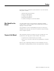
Preface Read this preface to familiarize yourself with the rest of the manual. The preface includes: • • • • • Who Should Use this Manual Who Should Use this Manual Purpose of this Manual Contents of this Manual Related Documentation Common Techniques Used in this Manual Use this manual if you are responsible for designing, installing, programming, or troubleshooting control systems that use SLC 500 High-Speed Counter Module.
P-2 Preface Contents of this Manual Refer to the following listing for the descriptive contents of this user manual. Chapter Publication 1746-UM006B-EN-P - August 2005 Title Contents Preface Describes the purpose, background, and scope of this manual. Also specifies the audience for whom this manual is intended. Chapter 1 Module Overview Explains and illustrates the theory behind the High-Speed Counter's operation. Covers hardware and software features.
Preface Related Documentation P-3 The following documents contain additional information concerning Rockwell Automation products. For Read this Document Document Number In-depth information on the SLC Instruction Set. SLC 500 Instruction Set Reference Manual 1747-RM001 A description on how to install and use your Modular SLC 500 programmable controller. SLC 500 Modular Hardware Style User Manual 1747-UM011 Information on reducing electrical noise.
P-4 Preface Publication 1746-UM006B-EN-P - August 2005
Chapter 1 Module Overview This chapter contains the following: • high-speed counter module overview • operating modes • hardware features High-Speed Counter Module Overview The High-Speed Counter Module, catalog number 1746-HSCE is an SLC 500 family compatible device except with the 1747-ASB Remote I/O Adapter Module. The high-speed module can be used with SLC 5/02 (and above) processors. The module’s bidirectional counting ability allows it to detect movement in either direction.
1-2 Module Overview Module operation is determined by selections made in the Setup and Control Word (M0:e.1). Setting the Function Control bit to 1 triggers the module to start the proper pulse counter, rate measurement, and output control functions. Many parameters are dynamic and can be changed without disrupting counter operation. A block diagram of the module is shown below. Inputs from the terminal block enter the diagram at the left, outputs to the terminal block exit at the right.
Module Overview Operating Modes 1-3 The module operates in 3 modes: • Range mode • Rate mode • Sequencer mode Specific operating mode information is contained in Chapter 2, Module Operation. The following information summarizes the module’s operating modes. IMPORTANT Appendixes D and E contain blank worksheets to assist you when configuring your module. Appendix D contains worksheets for Range and Rate Mode operation. Appendix E contains worksheets for the Sequencer Mode operation.
1-4 Module Overview Sequencer Mode In the Sequencer Mode, you define a sequence of presets and a series of corresponding output patterns. When the Accumulated Count passes the next preset, the outputs are updated to the corresponding pattern.
Module Overview 1-5 LEDs These LEDs illuminate when their corresponding input or output is active: • • • • LEDs 0-3 correspond to Physical Outputs 0-3. LEDs 4-7 correspond to Soft Outputs 4-7. LEDs A, B, Z, and LS indicate the input is energized. LED FAULT illuminates when the module is faulted. Input and Output Terminals These terminals supply power and inputs to the module and outputs to the attached output devices. They can accommodate two 14 AWG wires.
1-6 Module Overview Jumper JW1 JW1 selects the filtering rate used to debounce the limit switch input. Filtering rates are 300 µs and 10 ms. See Chapter 3 for default jumper setting.
Chapter 2 Module Operation This chapter describes the basic operation of the module. Specific programming information and individual memory maps for each mode are contained in Chapter 4.
2-2 Module Operation The above sources are determined by the Operating Mode and the Output Source Select fields. Module operation is determined by user-defined configuration parameters. Setting the Function Control bit to 1 starts the proper pulse counter, Rate Measurement, and output control functions. Dynamic parameters can be changed regardless of the Function Control bit. Static Parameters can be changed only when the Function Control bit is reset (to 0).
Module Operation Pulse and Direction Input 2-3 In this configuration, count pulses are applied to input A. The counter direction is controlled by either the Up/Down Count Direction bit, or by an external signal applied to input B (depending on the selection made in M0:e.1/9-11). When Pulse and Direction with External Control is chosen, the B input controls the direction (as illustrated below). If input B is low, the counter increments on the rising edges of input A.
2-4 Module Operation The count direction can be controlled from your user program rather than using a control signal connected to input B. This can be accomplished with the Up/Down Count Direction bit (M0:e.1/3) as follows: Up/Down Count Direction – bit 3 Up/Down Count Direction bit Bit Number (decimal) 15 14 13 12 11 10 9 8 Setup and Control Word, Word 1 7 6 5 4 3 2 1 0 M0:e.
Module Operation Quadrature Encoder Input 2-5 The figure below shows a quadrature encoder connected to inputs A, B, and Z. The count direction is determined by the phase angle between input A and input B. If A leads B, the counter increments. If B leads A, the counter decrements. The counter resolution can be selected so that the count increments/ decrements on one edge of input A only (X1), on both edges of input A (X2), or on both edges of input A and input B (X4).
2-6 Module Operation Up/Down Pulse Inputs With this input type, the counter increments on the rising edge of pulses applied to input A and decrements on the rising edge of pulses applied to input B. If pulses are applied to inputs A and B simultaneously, the pulse counter retains its previous value. The counter can be reset as described in Counter Reset Control on page 2-9. IMPORTANT Specific wiring information is contained in Chapter 3.
Module Operation Input Pulse Counter 2-7 The module’s input pulse counter has the ability to count input pulses at a rate of up to 50k Hz. Several types of channel A and B input configurations are supported as discussed previously. The resulting Accumulated Count value is available in the module’s Input Data File. Counter Types The module provides two types of counter operation, ring and linear. The selection is made by the Counter Type bit (M0:e.
2-8 Module Operation IMPORTANT If the reset value is nonzero, there is a delay of up to 500 µs before the reset value is loaded. Count pulses can be lost if they happen during the delay time. Refer to Timing Information in Appendix A. Ring Counter The figure below demonstrates ring counter operation. In ring counter operation, the count value goes between 0 and a maximum value. The maximum value must be entered in the Maximum Count Value (M0:e.34 Range and Rate Mode, M0:e.41 Sequencer Mode).
Module Operation 2-9 Counter Reset Control Reset Mode (bits 5,6,7) allows you to select the Accumulated Counter reset conditions. If the pulse counter is reset, the rate calculation is not affected. Bit 5 enables the Z reset, Bit 6 enables the limit switch reset, and bit 7 enables the Soft Reset. The counter can be reset from any combination of the Z input, LS input, or Soft Reset bit (M0:e.1/4). In the Sequencer Mode, you can reset the sequencer to the Initial Output pattern (M0:e.
2-10 Module Operation The reset of the counter is edge triggered. It occurs only when all of the conditions specified become true. If multiple conditions are selected, the counter is reset on the last event’s 0 to 1 transition. For example, if Z and LS are selected (011), Z by itself will not trigger the reset. Z and LS must both be ON. IMPORTANT The time it takes for the counter to reset depends upon the value it resets to.
Module Operation 2-11 Pulse Counter State When the SLC processor enters run or test mode, the Accumulated Count is reset to 0. It is held at 0 until the user program completes module configuration and the Function Control bit is set to 1. If the Function Control bit is reset to 0, the counter will again be reset and held at 0 until the Function Control bit returns to 1. The counter state is available to the user program in the Pulse Counter State field (I:e.0/14-15).
2-12 Module Operation Rate Measurement Calculation The module calculates the Rate Measurement by counting pulses in a fixed interval of time. You enter the fixed interval in the Rate Period parameter. This value is set in increments of 10 ms, from 10 ms to 2.55 seconds. The number of pulses counted in the interval is made available in the Rate Period Count word (I:e.2). Pulses increment or decrement the count.
Module Operation 2-13 Selecting the Rate Period Parameter The Rate Period parameter defaults to 0 and must be set to a value between 1 and 255 (10 ms to 2.55 seconds) to avoid a configuration error. Consider the following when selecting the Rate Period: • Make sure your Rate Period does not allow a Rate Counter Overflow to occur. This will depend on the maximum pulse frequency and input type.
2-14 Module Operation Output Control Physical and Soft Outputs The module provides 4 physical outputs. You select whether these outputs are to be activated from the user program or from the module in response to specified input events (refer to Output Source Select M0:e.0/0-7). The states of these 4 Physical Outputs are available to the user program in the Output Status field (I:e.4/8-11). In addition to the Physical Outputs, 4 Soft Outputs are available.
Module Operation 2-15 Range Outputs - Range and Rate Mode Physical Output patterns Bit Number (decimal) 15 14 13 12 11 10 9 8 7 6 5 4 3 2 1 0 Range 2 and 1 Outputs, Word 3 M0:e.3 M0:e.4 M0:e.5 M0:e.6 M0:e.7 M0:e.
2-16 Module Operation Output Start Up and Enabling When the SLC processor is not in run mode, the module outputs are disabled. After the SLC processor enters run mode, the module examines the Direct Output fields (O:e.0/0-7). All outputs under module control are disabled until after the module configuration has been completed and the Function Control bit has been set to 1. If the Function Control bit is returned to 0 the module controlled outputs will again be disabled.
Module Operation 2-17 Range Mode In the Range Mode, you use the counter ranges to specify the outputs to be active within each range. Ranges may overlap. The ranges are defined using the Starting and Ending Values (M0:e.10-33). The Range Outputs fields (M0:e.3-8) contain the output patterns that specify which outputs are active. Output patterns are applied to the Output Status field (I:e.4/8-15) and output terminals when the count is within the associated range (i.e.
2-18 Module Operation In this example, four ranges are specified. Configuration data for the counter is shown in the table. It indicates that output 0 is on for counts within range 1, output 1 is on for counts within range 2, output 2 is on for counts within range 3, and both outputs 0 and 3 are on for counts within range 4. When the count is 2000, outputs 2 and 1 are on, since 2000 falls within ranges 2 and 3. The figure below demonstrates Range Mode when a ring counter is used.
Module Operation 2-19 In the Range Mode, you use the counter ranges to specify the outputs to be active within each range. Ranges may overlap. The ranges are defined using the Starting and Ending Values (M0:e.10-33). The Range Outputs fields (M0:e.3-8) contain the output patterns that specify which outputs are active. Output patterns are applied to the Output Status field (I:e.4/8-15) and output terminals when the count is within the associated range (e.g.
2-20 Module Operation When using Rate Mode, use the Ring Counter and set the Reset Value/Maximum Count Value (M0:e.34)) to 32,767. Doing so allows the counter to roll over after reaching 32,767. If the Linear Counter counts beyond 32,767, it will cause an overflow (as explained in Linear Counter Overflow/Underflow located in Chapter 5). Appendix D contains blank worksheets to assist you when configuring your module for Rate Mode operation.
Module Operation 2-21 Sequencer Mode Use this mode when a repeatable sequence of events is required. This mode allows you to program a sequence of up to 24 steps. Configuration To define a step, you: • set a bit in the Valid Steps field which corresponds to the step • program the Step Preset value • program the Step Output value IMPORTANT Appendix E contains blank worksheets to assist you when configuring your module for Sequencer Mode operation. The Valid Steps (M0:e.2 to M0:e.
2-22 Module Operation The Initial Output (M0:e.3/8-15) is applied to the Physical and Soft Outputs only when the sequencer is initialized. Initialization occurs when the Function Control bit (M0:e.1/12) is toggled from 0 to 1, or when a pulse counter reset occurs and the Sequencer Reset bit (M0:e.1/0) is set to 1. IMPORTANT Although the Valid Steps can be dynamically changed by adding or removing steps while the Function Control bit (M0:e.
Module Operation 2-23 Sequencer Mode Operation A step is reached on the next count after the Accumulated Count matches the Step Preset value. When a step is reached, the Step Output value for that step is applied to the Physical and Soft Outputs. When the sequencer is first enabled (or reset), the Initial Output pattern (M0:e.3/8-15) is applied to the Physical and Soft Outputs. The module then proceeds through each step in the sequence in ascending order (1-24), as defined in the Valid Steps field (M0:e.
2-24 Module Operation Sequencer Mode with Ring Counter Rollover at 32,000 0 Preset 1 Sequence Begins Initial Outputs on Preset Preset 2 3 Rollover at 32,000 Preset 4 Preset 5 Preset 1 Sequence Repeats Counter Value Preset 1 Outputs Preset 2 Outputs Preset 3 Outputs Preset 4 Outputs Preset 5 Outputs Preset 1 Outputs Output 0 off Output 1 Output 2 Output 3 Preset Number Desired Trigger Preset Value Outputs (1) 7 6 5 4 3 2 1 0 Initial Output Repeat Sequence 0 0 0 0 0 0 0 0 1 10,000 9
Module Operation 2-25 An example of Sequencer Mode with a linear counter is shown below. Sequencer Mode with Linear Counter Accumulated Count 30,000 25,000 20,000 15,000 10,000 Reset Value 5,000 0 Reset Condition Sequencer Reset (M0:e.
2-26 Module Operation Publication 1746-UM006B-EN-P - August 2005
Chapter 3 Installation and Wiring This chapter provides the following information: • • • • • • • • Compliance to European Union Directives compliance to European Union directives dip switch and jumper location and settings module installation important wiring considerations input and outputs connections terminal block removal and wiring encoder wiring examples discrete devices and limit switch wiring examples If this product has the CE mark it is approved for installation within the European Union and
3-2 Installation and Wiring Dip Switch and Jumper Locations Two dip switches (SW1 and SW2) and one jumper (JW1) are located on the side of the module. • SW1 selects the type of input (single ended or differential). • SW2 selects the output voltage range (4.5-10V dc or 10-30V dc). • JW1 selects the filtering rate (300 µs or 10 ms) used to debounce the limit switch input.
Installation and Wiring SW2 Settings 3-3 Select an output voltage range that coincides with your supply voltage. The selections are 4.5-10V dc or 10-30V dc. ON 1234 OFF 10-30V dc ON Switch 1 2 3 4 Output 0 1 2 3 1234 OFF 4.5-10V dc ATTENTION All switches of SW2 must be ON or all switches must be OFF. Permanent damage may result if some are ON and some are OFF. Operating in the 10-30V dc range with the switches set for the 4.5-10V dc range will damage the module.
3-4 Installation and Wiring JW1 Settings Select 300 µs or 10 ms filtering to debounce the limit switch input. Position the jumper as follows: 321 321 JW1 JW1 10 ms Filter 300 us Filter The LS input allows you to make a direct connection to nominal voltage levels of 5, 12, or 24V dc. The ON voltage ranges are as follows: Wiring terminal Limit Switch ON range LS (24V dc) 16.5-30V dc LS (12V dc) 9.4- 10.5V dc LS (5V dc) 3.8-5.
Installation and Wiring Installing the Module 3-5 Installation procedures for this module are the same as any other discrete I/O or specialty module. IMPORTANT ATTENTION Set the dip switches before installing the module. Disconnect power before attempting to install, remove, or wire the module. Make sure your SLC power supply has adequate reserve current capacity. The module requires 320 mA at 5 volts. 1. Align the full sized circuit board with the rack card guide.
3-6 Installation and Wiring Important Wiring Considerations Use the following guidelines when planning the system wiring for the module: • Install the SLC 500 system in a NEMA rated enclosure. • Disconnect power to the SLC processor and the module before wiring. • Make sure the SLC 500 system is properly grounded. • Group this module and low voltage DC modules away from AC I/O or high voltage DC modules. • Shielded cable is required for high speed input signals A, B, and Z.
Installation and Wiring Input and Output Connections 3-7 Input and output wiring terminals are located on the front of the module, behind the terminal cover. When you connect input and output devices, you will also be concerned with the settings of dip switch SW1 (input connections), dip switch SW2 (output connections), and jumper JW1 (limit switch input connections). Refer to Dip Switch and Jumper Locations beginning on page 3-2 for the location and description of SW1, SW2, and JW1.
3-8 Installation and Wiring Outputs The module provides four Physical Outputs. They can be controlled by the module when certain counter conditions are met, or they can be controlled from the user program (refer to M0:e.0 in Chapter 4). The outputs are bipolar transistors connected in a sinking (open collector sinking) configuration. When the output is energized, it sinks the current. You can select an output voltage range of 4.5-10V dc or 10-30V dc.
Installation and Wiring Removing the Terminal Block 3-9 The removable terminal wiring block eliminates the need to rewire a module if it is removed from the rack. Each terminal will accept two #14 AWG wires. ATTENTION Disconnect power before attempting to install, remove, or wire the removable terminal wiring block. To avoid cracking the removable terminal block, alternate the removal of the slotted terminal block release screws.
3-10 Installation and Wiring Wiring the Removable Terminal Block The terminal screws can be turned with flat or cross slot screwdrivers. Each screw should be turned tight enough to immobilize the wire’s end. Over tightening can strip the terminal screw. The torque applied to each screw should not exceed 5.3 inch pounds. A wiring template for the terminal block is provided below.
Installation and Wiring Differential Encoder Wiring 3-11 Refer to your encoder manual for the proper cable type and length. Due to the topology of the module’s input circuits, terminating the shield at the encoder end provides the highest immunity to EMI interference. Connect EARTH ground directly to the encoder connector housing.
3-12 Installation and Wiring Single-Ended Encoder Wiring (Open Collector) Refer to your encoder manual for the proper cable type and length. Due to the topology of the module’s input circuits, terminating the shield at the encoder end provides the highest immunity to EMI interference. Connect EARTH ground directly to the encoder connector housing.
Installation and Wiring Single-Ended Encoder Wiring (Sourcing) 3-13 Refer to your encoder manual for the proper cable type and length. (The Allen-Bradley 845H sourcing encoder is not compatible with this module.) Due to the topology of the module’s input circuits, terminating the shield at the encoder end provides the highest immunity to EMI interference. Connect EARTH ground directly to the encoder connector housing.
3-14 Installation and Wiring Single-Ended Wiring (Discrete Devices) The following diagram shows the sensors operating from a common power supply. Separate power supplies for each circuit can be used.
Installation and Wiring 3-15 Limit Switch Wiring (24V dc Hard Contact) Hard Contact Limit Switch HSCE module LS (24V dc) LS (12V dc) VS + 24V dc LS (5V dc) – COM LS COM Do not connect LS (5V dc) or LS (12V dc) Terminals 321 JW1 Jumper placed for 10 ms filtering Limit Switch Wiring (12V dc Hard Contact) HSCE module Hard Contact Limit Switch LS (24V dc LS (12V dc) VS LS (5V dc) + 12V dc – LS COM COM Do not connect LS (5V dc) or LS (24V dc) Terminals 321 JW1 Jumper placed for 10 ms filtering
3-16 Installation and Wiring Publication 1746-UM006B-EN-P - August 2005
Chapter 4 Configuration and Programming This chapter contains the Output, Input and M0 file information.
4-2 Configuration and Programming M0 File Words - Range and Rate Modes For more information on M0 files, refer to Appendix B. Refer to Appendix D for Range and Rate Mode operation worksheets. IMPORTANT Reserved bits must be reset to 0.
Configuration and Programming 4-3 M0:e.0 Output Source Select Bit Number (decimal) M0 Word 0 15 14 13 12 11 10 9 8 7 6 5 4 3 2 1 Output Source Select Soft Outputs 0 M0:e.0 R R R R R R R R Output Source Select Physical Outputs M0:e.0 Bits 0 through 7 - Output Source Select (Dynamic) Bits 0, 1, 2, and 3 represent the Physical Outputs. Bits 4, 5, 6, and 7 represent the Soft Outputs.
4-4 Configuration and Programming M0:e1 Setup and Control Word Function Control 0 = Disable Counter 1 = Enable Counter Bit Number (decimal) Setup and Control Word, Word 1 Operating Mode 01 = Range 11 = Rate Counter Hold 1 = Hold Soft Reset 0 = False 1 = True 15 14 13 12 11 10 9 8 7 6 5 4 3 Enable Outputs 0 = Outputs OFF 1 = Outputs enabled 2 Counter Type 0 = Linear 1 = Ring 0 Reset Mode 000 = No reset 001 = Z 010 = LS 011 = LS and Z 100 = SR 101 = SR and Z 110 = SR and LS 111 = SR, LS, and
Configuration and Programming 4-5 M0:e.1 Bit 2 - Counter Hold (Dynamic) When set to 1, this bit prevents the pulse counter from counting input pulses. In addition, the Pulse Counter State bits in the Status Word (I:e.0/14-15) are set to Hold. Counter Hold (bit 2) Pulse Counter State 0 Pulses are passed to the pulse counter 1 Pulses are ignored The Counter Reset function and Rate Measurement are not affected when the Counter Hold bit is set. M0:e.
4-6 Configuration and Programming M0:e.1 Bit 4 - Soft Reset (Dynamic) The Soft Reset bit can be used to reset the counter in combination with the physical reset signals. Setting this bit (to 1) resets the counter, via the Reset Mode bits, if Soft Reset (bit 7) is selected. The 0 to 1 transition of the Soft Reset condition (M0:e.1/5-7) resets the counter when configured to do so (refer to Counter Reset Control in Chapter 2). Bit Number (decimal) 15 14 13 12 11 10 9 8 7 6 5 4 2 1 0 R M0:e.
Configuration and Programming 4-7 The reset of the counter is edge triggered. It occurs only when all of the conditions specified become true. If multiple conditions are selected, the counter is reset on the last event’s 0 to 1 transition. For example, if Z and LS are selected (011), Z by itself will not trigger the reset. Z and LS must both be ON. IMPORTANT The time it takes for the counter to reset depends upon the value it resets to.
4-8 Configuration and Programming M0:e.1 Bit 12 - Function Control (Dynamic) This bit enables and disables the counter function. Function Control bit Function 0 Disable counter (except user program controlled outputs) 1 Enable counter IMPORTANT The Function Control Bit must always be controlled by rungs in the ladder logic. Do not set the Function Control bit to 1 until all of your configured parameters are transferred. Never save the program with the Function Control bit set. Enable ] [ M0:e.
Configuration and Programming 4-9 The user program can change the Function Control bit dynamically in either the run or test modes to reconfigure or control the operation. You can change the preset or range information at any time independent of this bit. Refer to Timing Information in Appendix A. M0:e.1 Bit 13 - Counter Type (Static) This bit allows you to define the module’s Counter Type: Counter Type (bit 13) Counter Type 0 Linear 1 Ring M0:e.
4-10 Configuration and Programming M0:e.2 Valid Ranges (Dynamic) The Range and Rate Modes support 12 different ranges. This word is used to enable Range Outputs fields. Valid Ranges Bit Number (decimal) Setup and Control Word, Word 1 Range 15 14 13 12 11 10 9 8 7 6 5 4 3 2 1 0 M0:e.2 R R R R 12 11 10 9 8 7 6 5 4 3 2 1 M0:e.2 Bits 0 through 11 - Valid Ranges Bits 0 through 11 represent ranges 1 through 12 respectively. When a bit is set to 1, the range it represents is enabled.
Configuration and Programming 4-11 M0:e.3 through M0:e.8 - Range 1 through 12 Outputs (Dynamic) Use these words to program specific on/off output patterns. The Range 1 through Range 12 Outputs, shown below, are associated with Ranges 1 through 12 respectively. Each output field consists of 8 bits. The four lowest numbered bits correspond to the module’s Physical Outputs. The four highest numbered bits correspond to the Soft Outputs.
4-12 Configuration and Programming M0:e.9 Bits 0 through 7 This value represents the interval (Rate Period) of which the Rate Calculation will be performed. The integer value entered in bits 0-7 can range from 1-255. It is multiplied by 10ms to obtain the actual Rate Period time. If reset to 0, a fault will occur. Refer to Selecting the Rate Period Parameter in Chapter 2. M0:e.9 Bits 8 through 15 Bits 8 through 15 are reserved and must be reset to 0. M0:e.10 through M0:e.
Configuration and Programming 4-13 The Range Starting Value specifies the start of the range and the Range Ending Value specifies the end. While using the Ring Counter Type and the Starting > Ending, the range extends across the rollover count (Maximum Count Value). While using the Linear Counter Type and the Starting > Ending, the range extends from Starting to 32767 and from -32767 to Ending. Refer to the Range Mode with Linear Counter example in Chapter 2. Ranges may overlap.
4-14 Configuration and Programming Reset Value When the module is configured for a linear counter, the counter is reset to the value you enter in this word. This word allows you to initialize the counter, when a reset condition occurs, to a specific value other than zero. The range of this value is -32767 to +32767. The example below illustrates reset values of -32,767 and +32,767.
Configuration and Programming 4-15 O:e.0 Bits 0 through 7 - Direct Outputs These bits are used for direct user program control of the outputs. Bits 0, 1, 2, and 3 represent the four Physical Outputs of the module. When one of these bits is set, the corresponding output circuit is ON if that output is under user program control (refer to M0:e.0 Output Source Select on page 4-3).
4-16 Configuration and Programming I:e.0 Status Word Rate Measurement Overflow Reset Input 0 = False Reset Mode 1 = True Reset Mode Bit Number (decimal) 15 14 13 12 11 10 9 8 7 6 5 4 3 R R R R Status Word, Word 0 Zero Rate Period Count 0 = Nonzero Rate Period count 1 = Rate Period Count is 0 0 = No overflow 1 = Overflow Configuration Error 0 = No configuration error 1 = Invalid configuration data 2 1 0 R R I:e.
Configuration and Programming 4-17 I:e.0 bit 3 - Rate Valid This bit is cleared upon the 0 to 1 transition of the Function Control bit. The module sets this bit to 1 when the Rate Measurement and Rate Period Count inputs have valid values that do not cause any overflows. The bit is updated after every Rate Period.
4-18 Configuration and Programming I:e.0 Bit 5 - Rate Measurement Overflow When this bit is set to 1, one of the following conditions exist: • The calculated Rate Measurement input parameter exceeds the maximum rate of ± 32767 Hz. • A Rate Period Counter overflow is detected. The bit is dynamically updated after every Rate Measurement. When the overflow occurs, the Rate Period will be set to ±32767 Hz.
Configuration and Programming 4-19 The error bit is cleared when the Function Control Bit is toggled to 0, then back to 1. Critical Error (bit 10) Cause 0 No Critical Error detected 1 Critical Error detected I:e.0 Bit 11 - Configuration Error This bit is set to 1 when a configuration error is detected. In addition, the Configuration Error Code bits (I:e.4/0-7) are set. This bit remains set as long as invalid configuration data exists in the Setup and Control Word (M0:e.1).
4-20 Configuration and Programming I:e.0 Bit 13 - Overflow/Underflow When this bit is set, it indicates that the linear counter has overflowed or underflowed. The module controlled outputs are reset to 0 while this error is present. The bit can be cleared by toggling the Function Control Bit (M0:e.1/12) to 0 and then back to 1. This is a Critical Error. Overflow/Underflow (bit 13) Cause 0 No overflow/underflow detected 1 Linear counter has overflowed or underflowed I:e.
Configuration and Programming 4-21 I:e.2 Rate Period Count The Rate Period Count is generated by the Rate Counter. This word indicates the number of counts obtained during the last Rate Measurement Period. This input value is active in all modes. It is updated along with the Rate Measurement. It will not be scaled down when using the x2 or x4 input type. Bit Number (decimal) Rate Period Count, Word 2 15 14 13 12 11 10 9 8 7 6 5 4 3 2 1 0 I:e.2 I:e.
4-22 Configuration and Programming I:e.
Configuration and Programming 4-23 I:e.6 Range Active Bits 0-11 of this word indicate which range, or ranges are currently active. A range is active whenever the current Accumulated Count (I:e.1 for Range Mode) or Rate Measurement (I:e.3 for Rate Mode) is equal to or within the Starting or Ending Value of a range. Whenever this condition is true, the bit associated with the range will be set to 1. For an inactive range, the associated bit is logic 0.
4-24 Configuration and Programming M0 File Words - Sequencer Mode For more information on M0 files, refer to Appendix B. Refer to Appendix E for Sequencer Mode operation worksheets. Output Source Select Bit Number (decimal) 15 14 13 12 11 10 9 Output Source Select, Word 0 Setup and Control Word, Word 1 Valid Steps 1–16, Word 2 Initial Outputs and Valid Steps 17–24, Word 3 8 7 6 5 4 3 2 1 0 RR RR R R R R R R RR M0:e.0 M0:e.1 M0:e.2 M0:e.3 M0:e.4 M0:e.
Configuration and Programming 4-25 M0:e.0 Bits 0 through 7 - Output Source Select (Dynamic) Bits 0, 1, 2, and 3 represent the Physical Outputs. Bits 4, 5, 6, and 7 represent the Soft Outputs. The status of these bits determines whether an output is controlled by the module (when the Function Control bit is set to 1), or by the user program.
4-26 Configuration and Programming M0:e.1 Bit 0 - Sequencer Reset (Dynamic) This bit determines whether the sequencer is reset each time the counter is reset. If the pulse counter is reset when this bit is set to 1, the sequencer resets. In addition: • The Current Sequencer Step (I:e.4/0-7) is reset to zero. • The Next Sequencer Step Preset (I:e.7) is reset to the preset of the first valid step. • The Initial Output pattern (M0:e.3/8-15) is sent to the outputs.
Configuration and Programming 4-27 M0:e.1 Bit 2 - Counter Hold (Dynamic) When set to 1, this bit prevents the pulse counter from counting input pulses. In addition, the Pulse Counter State bits in the Status Word (I:e.0/14-15) are set to Hold. Counter Hold (bit 2) Pulse Counter State 0 pulses are passed to the pulse counter 1 pulses are ignored The Counter Reset function and Rate Measurement are not affected when the Counter Hold bit is set. M0:e.
4-28 Configuration and Programming M0:e.1 Bits 5,6,7 - Reset Mode (Static) These bits allow you to select the device(s) that reset the counter. Bit 5 enables the Z reset, Bit 6 enables the limit switch reset, and bit 7 enables the soft reset, as shown below: Reset Mode bits Bit Number (decimal) 15 14 13 12 11 10 9 8 7 6 5 4 3 2 R Setup and Control Word, Word 1 1 0 R M0:e.
Configuration and Programming 4-29 The reset of the counter is edge triggered. It occurs only when all of the conditions specified become true. If multiple conditions are selected, the counter is reset on the last event’s 0 to 1 transition. For example, if Z and LS are selected (011), Z by itself will not trigger the reset. Z and LS must both be ON. IMPORTANT The time it takes for the counter to reset depends upon the value it resets to.
4-30 Configuration and Programming M0:e.1 Bit 12 - Function Control (Dynamic) This bit enables and disables the counter function. Function Control bit Function 0 Disable counter (except user program controlled outputs) 1 Enable counter IMPORTANT The Function Control Bit must always be controlled by rungs in the ladder logic. Do not set the Function Control bit to 1 until all of your configured parameters are transferred. Never save the program with the Function Control bit set. Enable ] [ M0:e.
Configuration and Programming 4-31 The user program can change the Function Control bit dynamically in either the run or test modes to reconfigure or control the operation. Note that you can change the preset or range information at any time independent of this bit. Refer to Timing Information in Appendix A. M0:e.1 Bit 13 - Counter Type (Static) This bit allows you to define the Counter Type: Counter Type (bit 13) Counter Type 0 linear 1 ring M0:e.
4-32 Configuration and Programming steps 1–16 Bit Number (decimal) 15 14 13 12 11 10 9 8 7 6 5 4 3 2 1 0 M0:e.2 M0:e.3 Valid Steps 1–16, Word 2 Initial Outputs and Valid Steps 17–24, Word 3 steps 17–24 Valid Steps for Sequencer Mode Corresponding Step 0 disabled 1 enabled M0:e.3 /8-15 Initial Outputs (Dynamic) The Initial Output is the starting position output pattern. It determines the output pattern until the preset of the first Valid Step is reached.
Configuration and Programming 4-33 M0:e.4 through M0:e.15-Step 1 through 24 Outputs (Dynamic) M0:e.4 through M0:e.15 are used to program the specific ON/OFF output patterns for each of the 24 possible steps. Each output field consists of 8 bits. The four lowest numbered bits correspond to the Physical Outputs of the module; the four highest numbered bits correspond to the Soft Outputs. For example, in Preset 2 Outputs of word M0:e.
4-34 Configuration and Programming M0:e.16 Bits 0 through 16 - Rate Period The integer value in this word indicates the Rate Period time. The value can range from 1-255. This value is multiplied by 10 ms to obtain the actual Rate Period time. For more information, refer to Selecting the Rate Period Parameter in Chapter 2. M0:e.16 Bits 8 through 15 Bits 8 through 15 are reserved and must be reset to 0. M0:e.17 through M0:e.40 Step 1 through 24 Presets (Dynamic) The Sequencer Mode supports 24 steps.
Configuration and Programming 4-35 M0:e.41 Maximum Count (Static) / Reset Value (Dynamic) Bit Number (decimal) 15 14 13 12 11 10 9 8 7 6 5 4 3 2 1 Maximum Count / Reset Value 0 M0:e.41 Maximum Count When the module is configured as a Ring Counter type, this word allows you to specify the ring rollover count. The range of this value is 1 to +32767. If 0, a configuration error occurs. The example below specifies a rollover count of 32,767.
4-36 Configuration and Programming Output Data File Word Sequencer Mode The Output Data File is only one word in size. Appendix E contains worksheets for Sequencer Mode operation. O:e.0 Direct Outputs (Dynamic) Direct Outputs Reserved Bit Number (decimal) Direct Outputs, Word 0 15 14 13 12 11 10 9 8 7 6 5 4 3 2 1 0 O:e.0 R R R R R R R R Direct user program control of Soft Outputs Direct user program control of Physical Outputs O:e.
Configuration and Programming Input Data File Words Sequencer Mode 4-37 The figure below shows how the input data file words are used. An explanation of each word follows the figure.
4-38 Configuration and Programming I:e.0 Bit 2 - Zero Rate Period Count The module sets this bit to 1 whenever the Rate Period Count is found to be zero over a Rate Period.
Configuration and Programming 4-39 I:e.0 Bit 4 - Rate Counter Overflow When this bit is set, a Rate Period Counter overflow has been detected. The bit is dynamically updated after every Rate Period. You can adjust the Rate Period when an overflow is detected. When the overflow occurs, the Rate Period will be set to ±32767. Refer to Rate Counter Overflow in Chapter 5.
4-40 Configuration and Programming I:e.0 Bit 6 - Sequence Done This bit is set whenever the end of sequence is reached. This bit is set (and remains set) as long as the last preset output data is in effect. This bit is cleared when the last preset output data is not in effect. Sequence Done (bit 6) Cause 0 preset is valid 1 end of sequence I:e.0 Bits 7,8,9 Bits 7, 8, and 9 are reserved and must be reset to 0. I:e.
Configuration and Programming 4-41 I:e.0 Bit 11 - Configuration Error This bit is set to 1 when a configuration error is detected. In addition, the Configuration Error Code bits (I:e.4/0-7) are set. This bit remains set as long as invalid configuration data exists in the Setup and Control Word (M0:e.1). Configuration Error (bit 11) Cause 0 no configuration error detected 1 configuration error detected I:e.
4-42 Configuration and Programming I:e.0 Bits 14 and 15 - Pulse Counter State These bits indicate the current state of the Pulse Counter (the state of the Rate Counter is separate): Pulse Counter State Bits Pulse Counter State 15 14 0 0 stopped 0 1 running 1 0 undefined 1 1 hold I:e.1 Accumulated Count This is the input value from the pulse counter. It gives the total number of counts since the pulse counter was last reset (plus the reset value).
Configuration and Programming 4-43 I:e.3 Rate Measurement (Hz) This word indicates the current rate at which the count is being received (in Hz). This value is updated after every Rate Period. This input value is active in all modes. When the module is used with encoders and configured for x2 or x4 input types, the calculated value will be scaled down by a factor or two or four respectively. Bit Number (decimal) Rate Measurement Word 3 15 14 13 12 11 10 9 8 7 6 5 4 3 2 1 0 I:e.3 I:e.
4-44 Configuration and Programming I:e.4 Bits 8 through 15 - Output Status These bits reflect the current state of both the Soft and Physical Outputs. If the Enable Output bit (M0:e.1/1) is false or if the processor is not in run mode, the Physical Outputs are not active. Bits 8-11 represent the Physical Outputs 0-3. Bits 12-15 represent the Soft Outputs 4-7. I:e.
Configuration and Programming 4-45 I:e.6 Reserved I:e.7 Next Sequencer Step Preset This word indicates the next step preset value. When the pulse counter passes this value, the sequencer advances to the Next Sequencer Step. Bit Number (decimal) Next Sequencer Step Preset, Word 7 15 14 13 12 11 10 9 8 7 6 5 4 3 2 1 0 I:e.
4-46 Configuration and Programming Publication 1746-UM006B-EN-P - August 2005
Chapter 5 Start-Up, Operation, and Troubleshooting This chapter provides start-up, operation, troubleshooting, and error handling information. Start-Up The following steps will assist you in the start up of your module. 1. Install the module in your SLC chassis. 2. Wire the input and output devices as discussed in Chapter 3. 3. Configure and program your SLC processor to operate with the module as discussed in Chapter 4. 4. Apply power to the SLC system and the attached input and output devices.
5-2 Start-Up, Operation, and Troubleshooting turn on and off indicating input signal status OUTPUT INPUT turn on and off indicating Physical Output status 0 4 A Z 1 5 B LS 2 6 3 7 Fault LED OFF FAULT HSCE Troubleshooting turn on and off indicating Soft Output status The key tools in diagnosing problems are: • • • • • module LEDs SLC processor CPU fault LED SLC processor fault code (S:6) Status Word in the module’s Input Data File (I:e.
Start-Up, Operation, and Troubleshooting Error Handling 5-3 In addition to the SLC processor system fault, the following three module generated errors can occur: • Module Diagnostic errors • Module Configuration Errors • Application Errors SLC System Fault If a fault has occurred in the SLC system and the SLC fault code indicates the slot the module is installed in, it might be associated with the module I/O configuration. Refer to the following table.
5-4 Start-Up, Operation, and Troubleshooting The parameter that caused the error is indicated in the Configuration Error Code field (I:e.4/0-7). The table below lists the configuration error code and indicates the required action to clear the error.
Start-Up, Operation, and Troubleshooting IMPORTANT 5-5 When this bit is set, the Rate Measurement Overflow bit (I:e.0/5) is set. Rate Measurement Overflow When the Rate Measurement exceeds 32,767 Hz, the Rate Measurement overflow bit (I:e.0/5) is set to 1. The module will continue to run the rate measurement calculation and will clear the error if the input frequency drops below 32,767 Hz. If operating in the Rate Mode, the module controlled outputs are reset to 0 while this error is present.
5-6 Start-Up, Operation, and Troubleshooting Output Does Not Come On Make sure SLC processor is in run mode. Check the associated module LED for the output. • If the LED is illuminated check the power supply and its connections to the module. Also check the connections to the output device. • If the LED is not illuminated make sure the SLC processor is in run mode and that a module fault has not occurred. Check the Output Status field of the input image (I:e.
Chapter 6 Application Examples This chapter contains the following application examples: • a basic count-only example using the Rate Mode • supplementary examples that represent the Range, Rate, and Sequencer Modes IMPORTANT Basic Count-Only Example Appendixes D and E contain blank worksheets to assist you when configuring your module. Appendix D contains worksheets for Range and Rate Mode operation. Appendix E contains worksheets for the Sequencer Mode operation.
6-2 Application Examples The following is a brief description of the application. • The processor monitors the number of pulses that the module has counted. If this number is greater than or equal to 2500, bit B3/0 is energized. If this number is less than 2500, bit B3/1 is energized. • If the count reaches 30,000 the accumulator of the module resets to zero automatically. • If you press the Reset Push Button, the accumulator of the module is reset, regardless of the current count.
Application Examples 6-3 Setup and Control Word (page 4-4) The module will fault on power-up if you do not enter a value. ATTENTION Counter Type (page 4-9) Operating Mode (page 4-9) Soft Reset (page 4-6) Function Control (page 4-8) Counter Hold (page 4-5) Reset Mode (page 4-6) Input Type (page 4-7) Enable Outputs (page 4-4) Up/Down Count Direction (page 4-5) Valid Ranges (page 4-10) The module will fault on power-up if you do not enter a value.
6-4 Application Examples Range Outputs (page 4-11) Bit Number (decimal) Output Number 15 14 13 12 11 10 9 8 7 6 5 4 3 2 1 0 7 6 5 4 3 2 1 0 7 6 5 4 3 2 1 0 Range 2 Outputs Range 1 Outputs M0:e.3 Range 4 Outputs Range 3 Outputs M0:e.4 Range 6 Outputs Range 5 Outputs M0:e.5 Range 8 Outputs Range 7 Outputs M0:e.6 Range 10 Outputs Range 9 Outputs M0:e.7 Range 12 Outputs Range 11 Outputs M0:e.
Application Examples 6-5 Starting and Ending Range Values (decimal) (page 4-12) Range 1 Starting Value M0:e.10 Range 1 Ending Value M0:e.11 Range 2 Starting Value M0:e.12 Range 2 Ending Value M0:e.13 Range 3 Starting Value M0:e.14 Range 3 Ending Value M0:e.15 Range 4 Starting Value M0:e.16 Range 4 Ending Value M0:e.17 Range 5 Starting Value M0:e.18 Range 5 Ending Value M0:e.19 Range 6 Starting Value M0:e.20 Range 6 Ending Value M0:e.21 Range 7 Starting Value M0:e.
6-6 Application Examples User Program Shown below is the user program for the Count-Only example. Rung 2:1 | 1’st Initialize | | Pass module | | | | S:1 +COP–––––––––––––––+ | |––––] [––––––––––––––––––––––––––––––––––––––––––––––––––+COPY FILE +–| | 15 |Source #N10:0| | | |Dest #M0:1.0| | | |Length 42| | | +––––––––––––––––––+ | Rung 2:2 | 1’st Function | | Pass Control | | Bit | | S:1 M0:1.
Application Examples Supplementary Examples 6-7 This section contains three application examples that represent the Range, Rate, and Sequencer Modes. Each example has a description, timing information, and configuration worksheets. Additional worksheets are contained in appendixes D and E. Range Mode-Drilling Example In this example a hole is drilled into a piece of stock. The drill bit is spun by a single speed, single direction motor that is controlled by the module.
6-8 Application Examples The following is a brief description of the application. • The drill (O:1/1) and feed motors (O:2/0 and O:2/1) are off. The drill is in the home position (limit switch is open). • The feed motor (O:2/0) moves forward in the slow speed until count 49. • At count 50, the drill moves forward in the fast speed (O:1/2). • At count 10,000 the drill bit begins turning (O:1/1). • At count 10,250 the feed motor returns to the slow speed (O:1/2).
Feed motor Forward Stop O:1/0 Drill O:1/1 Speed O:1/2 Feed Motor Forward O:2/0 Feed Motor Reverse O:2/1 1 = Stop 1 = ON 0 = OFF 1 = Fast 0 = Slow Forward Stop Detect 1 = Stop I:1.4/15 0 = Moving 0 = OFF 1 = ON 0 = OFF 1 = ON Accumulated count 0 50 Forward Direction 10,000 10,250 Drill motor stops Feed motor returns to slow speed, reverse direction Limit switch opens, feed motor stops Drill moves to home positio n 11,000 Feed motor changes to fast speed, reverse direction 10.
6-10 Application Examples Configuration Worksheets Shown below is the Range/Rate Mode Configuration Worksheet. A blank worksheet is supplied in Appendix D. Direct Outputs (page 4-15) Output Source Select (page 4-3) Setup and Control Word (page 4-4) ATTENTION Counter Type (page 4-9) Operating Mode (page 4-9) The module will fault on power-up if you do not enter a value.
Application Examples 6-11 Valid Ranges (page 4-10) The module will fault on power-up if you do not enter a value. ATTENTION Range Outputs (page 4-11) Rate Period (decimal) (page 4-11) The module will fault on power-up if you do not enter a value. ATTENTION Rate Period 0 1 0 M0:e.9 R = Reserved, must be reset to 1 to 255 = 10 ms to 2.
6-12 Application Examples Starting and Ending Range Values (decimal) (page 4-12) 0 M0:e.10 4 9 M0:e.11 Range 1 Starting Value Range 1 Ending Value 5 0 M0:e.12 Range 2 Ending Value 1 0 2 4 9 M0:e.13 Range 3 Starting Value 1 0 2 5 0 M0:e.14 Range 3 Ending Value 1 9 9 9 9 M0:e.15 Range 4 Starting Value 1 0 0 0 0 M0:e.16 Range 4 Ending Value 1 9 9 9 9 M0:e.17 Range 5 Starting Value 1 1 0 0 0 M0:e.18 Range 5 Ending Value 1 9 9 9 9 M0:e.
Application Examples 6-13 Shown below is the Range/Rate Mode Configuration Worksheet for the Input File. A blank worksheet is supplied in Appendix D. The data contained in the Input Data File varies, depending on the range that is active. The following cross section of time was taken within Ranges 2 and 4.
6-14 Application Examples Output Status and Configuration Error Code Range Active Bit Number (decimal) 15 14 13 12 11 10 9 Range Active R R R R 0 0 0 Range Number 7 6 5 3 2 1 0 8 0 0 0 0 4 0 1 0 1 0 12 11 10 9 8 7 6 5 4 3 2 1 Range Active 1 = Range Active Module Setup Information Module ID Code = 12705 (8 Input and 1 Output word) 42 M0 file words File size - 42 word integer file, 42 word M0 File Publication 1746-UM006B-EN-P - August 2005 I:e.
Application Examples 6-15 User Program Shown below is the user program for the drilling example. Rung 2:0 | 1’st Initialize | | Pass HSC | | | | S:1 +COP–––––––––––––––+ | |––––] [––––––––––––––––––––––––––––––––––––––––––––––––––+COPY FILE +–| | 15 |Source #N10:0| | | |Dest #M0:1.0| | | |Length 42| | | +––––––––––––––––––+ | Rung 2:1 | 1’st | | Pass | | S:1 M0:1.
6-16 Application Examples Configuration Data Tables Shown below is the configuration information for the Drilling example in Binary and Decimal radixes.
Application Examples 6-17 Decimal Radix Publication 1746-UM006B-EN-P - August 2005
6-18 Application Examples Rate Mode-Log Ripper Example In the following rate example, a variable speed conveyor is being used to feed logs into a saw blade. An encoder is connected to the motor shaft. As the shaft turns, the encoder generates pulses and sends them to the module. The module uses the pulses to calculate the rate of the sawblade in Hz. The conveyor has two speeds, fast and slow. At location #1 (refer to speed/time chart below) logs are fed into the saw blade at the fast speed.
Application Examples 6-19 Configuration Worksheets Shown below is the Range/Rate Mode Configuration Worksheet for M0 Files. A blank worksheet is supplied in Appendix D. Direct Outputs (page 4-15) Output Source Select (page 4-3) Setup and Control Word (page 4-4) ATTENTION Counter Type (page 4-9) Operating Mode (page 4-9) The module will fault on power-up if you do not enter a value.
6-20 Application Examples Valid Ranges (page 4-10) The module will fault on power-up if you do not enter a value. ATTENTION Bit Number (decimal) 15 14 13 12 11 Range Number R Valid Range R R R 8 7 6 5 4 3 2 1 0 12 11 10 9 10 8 7 6 5 4 3 2 1 0 0 0 0 0 0 1 1 0 9 0 0 0 M0:e.2 1 = range is valid. At least one range must be valid.
Application Examples 6-21 Starting and Ending Range Values (decimal) (page 4-12) Range 1 Starting Value Range 1 Ending Value 4 0 0 0 M0:e.10 9 9 9 9 M0:e.11 0 M0:e.12 9 M0:e.13 Range 2 Starting Value Range 2 Ending Value 3 9 9 Range 3 Starting Value M0:e.14 Range 3 Ending Value M0:e.15 Range 4 Starting Value M0:e.16 Range 4 Ending Value M0:e.17 Range 5 Starting Value M0:e.18 Range 5 Ending Value M0:e.19 Range 6 Starting Value M0:e.20 Range 6 Ending Value M0:e.
6-22 Application Examples Reset Value/Maximum Count Value (page 4-13) The module will fault on power-up if you do not enter a value. ATTENTION Reset Value/Maximum Count Value 3 2 7 6 7 M0:e.34 Ring counter – Maximum Count Value range is 1 to 32767 (rollover at +32767) Linear counter – Reset Value range is –32767 to +32767. Shown below is the Range/Rate Mode Configuration Worksheet for the Input File. A blank worksheet is supplied in Appendix D.
Application Examples 6-23 Accumulated Count, Rate Period Count, and Rate Measurement (decimal) Accumulated Count 9 8 7 6 I:e.1 Rate Period Count 1 9 5 0 I:e.2 Rate Measurement (Hz) 6 5 0 0 I:e.3 Output Status and Configuration Error Code Bit Number (decimal) 15 14 13 12 Output Status and Configuration Error Code 1 0 0 0 Output Number 7 6 5 4 11 10 0 0 0 2 1 3 9 8 0 7 6 R R 4 3 2 1 0 R R 5 0 0 0 0 I:e.
6-24 Application Examples User Program Shown below is the user program for the Log Ripper example. Rung 2:0 | Start Stop Saw Saw Motor | | Saw | | I:2.0 I:2.0 O:3.0 | |–+––––] [–––––+––––]/[––––––––––––––––––––––––––––––––––––––––––––––––( )–––––| | | 0 | 1 0 | | | Saw | | | | Motor | | | | O:3.
Application Examples 6-25 Configuration Data Tables Shown below is the configuration information for the Log Ripper example in Binary and Decimal radixes.
6-26 Application Examples Decimal Radix Publication 1746-UM006B-EN-P - August 2005
Application Examples 6-27 Sequencer Mode - Cut to Length Example In this example, flat steel is fed into a cutter. Using the Sequencer Mode, it is cut to a specific length. The application consists of a motor, motor interface, encoder, clutch/brake, and cutter. A quadrature encoder is connected directly to the motor shaft. It sends pulses to the module. The module controls the motor interface. The motor interface controls the motor speed, the user program enables the motor.
6-28 Application Examples The following is a brief description of the application. 150 14,000 18,000 Cutter is de–energized Brake enabled (cluth disengages) Cutter is energized Module releases brake Clutch engages Motor switches to low speed High Speed O:1/1 Motor switches to high speed Motor Enable O:1/0 . User program starts motor Encoder starts sending pulses Power up • The Initial Outputs (M0:e.3/8-15) are reset to 0.
Application Examples 6-29 Configuration Worksheets Shown below is the Sequencer Mode Configuration Worksheet for the Output and M0 File. A blank worksheet is supplied in Appendix E. Direct Outputs (page 4-36) Bit Number (decimal) 15 14 13 12 11 10 9 8 Output Number R Direct Outputs R R R R R R R 7 6 5 4 3 2 1 0 7 6 5 4 3 2 1 0 0 0 0 0 0 0 0 0 O:e.
6-30 Application Examples Valid Steps (page 4-31) The module will fault on power-up if you do not enter a value. ATTENTION Bit Number (decimal) 15 Step Number 8 7 6 5 4 3 2 1 0 16 15 14 13 12 11 10 9 8 7 6 5 4 3 2 1 0 0 0 1 1 1 1 1 M0:e.2 0 0 0 0 0 0 0 M0:e.3 0 Valid Steps 1 – 16 14 0 13 0 12 0 11 0 10 0 9 0 0 Initial Outputs and Valid Steps 17 – 24 0 1 = Valid Step. At least one preset must be valid.
Application Examples 6-31 Shown below is a Sequencer Mode Configuration Worksheet for Step Output information. Based on your application, you enter the Step Outputs, Step Preset Values, and Reset Value/Maximum Count Value into the appropriate places on the worksheet. When you begin programming, you can transcribe the information contained in the worksheet to your data files. A blank worksheet is supplied in Appendix E.
6-32 Application Examples Step Preset Values (decimal) (page 4-34) 9 9 M0:e.17 Step 13 Preset M0:e.29 1 4 9 M0:e.18 Step 14 Preset M0:e.30 9 9 9 M0:e.19 Step 15 Preset M0:e.31 Step 16 Preset M0:e.32 Step 1 Preset Step 2 Preset Step 3 Preset 1 3 Step 4 Preset 1 7 9 9 9 M0:e.20 Step 5 Preset 1 8 9 9 9 M0:e.21 Step 17 Preset M0:e.33 Step 6 Preset M0:e.22 Step 18 Preset M0:e.34 Step 7 Preset M0:e.23 Step 19 Preset M0:e.35 Step 8 Preset M0:e.
Application Examples 6-33 Status Word Configuration Error (page 4-41) Rate Counter Overflow (page 4-39) Zero Rate Period Count (page 4-38) Overflow/Underflow (page 4-41) 0 = No error detected 1 = Overflow/Underflow Bit Number (decimal) Status Word 0 = No configuration error 1 = Invalid configuration data 15 14 13 12 11 10 9 8 7 0 1 0 0 0 0 R R R Pulse Counter State (page 4-42) Reset Input (page 4-41) 00 = Stopped 01 = Running 10 = Undefined 11 = Hold 0 = No overflow 1 = Overflow 6
6-34 Application Examples Next Sequencer Step and Current Sequencer Step Bit Number (decimal) 15 0 14 0 13 0 12 0 11 10 0 0 9 1 8 7 1 6 0 5 0 Next Sequencer Step 0 4 0 3 2 1 0 0 1 Current Sequencer Step Next Sequencer Step Preset (decimal) Next Sequencer Step Preset 1 3 9 9 9 I:e.7 Module Setup Information Module ID Code = 12705 (8 Input and 1 Output word) File Size - 42 word integer file, and 42 word M0 File Publication 1746-UM006B-EN-P - August 2005 0 0 I:e.
Application Examples 6-35 User Program Shown below is the user program for the Cut to Length example. Rung 2:0 | 1’st pass Initialize | | High-Speed | | Counter | | S:1 +COP–––––––––––––––+ | |––––] [––––––––––––––––––––––––––––––––––––––––––––––––––+COPY FILE +–| | 15 |Source #N10:0| | | |Dest #M0:1.0| | | |Length 42| | | +––––––––––––––––––+ | Rung 2:1 | Machine Enable HSC SEQ | | (enables/disables Function Control bit) Enable | | B3 M0:1.
6-36 Application Examples Configuration Data Tables Shown below is the configuration information for the Cut to Length example in Binary and Decimal radixes.
Application Examples 6-37 Decimal Radix Publication 1746-UM006B-EN-P - August 2005
6-38 Application Examples Publication 1746-UM006B-EN-P - August 2005
Appendix A Specifications General Description Specification Operating Temperature 0 °C to +60 °C (+32 °F to +140 °F) Storage Temperature -40 °C to +85 °C (-40 °F to +185 °F) Humidity 5 to 95% without condensation Backplane Current Consumption (power supply loading) 320 mA at +5V 0 mA at +24V Maximum Cable Length (1) 305 m (1000 ft) Agency Certification (when product or packaging is marked) • CSA certified • CSA Class I, Division 2 Groups A, B, C, D certified • UL listed • CE marked for all
A-2 Specifications Limit Switch Input Outputs (Open Collector, Sinking) Description Specification 5V dc 12V dc 24V dc On-State Voltage 3.8 to 5.4V dc 9.4 to 16.5V dc 16.5 to 30V dc Off-State Voltage 0 to 1.2V dc 0 to 2.4V dc 0 to 3.9V dc Input Current minimum nominal maximum 4.6 mA 6.8 mA 9.2 mA Max. Off-State Leakage Current 1 mA (all ranges) Isolation (from backplane) 1500 volts Specification Description 4.5 to 10V dc (Switch 2 on) 10 to 30V dc (Switch 2 off) Max.
Specifications Operation Description Timing(2) Z input reset response time. Reset to a value other than zero (0) The time required for the module to respond to an external Z input event and reset the pulse counter to a value other than 0. 500 µs (3) A-3 Limit switch reset response time. The time required for the module to respond to an external limit Reset to zero (0) switch event and reset the pulse counter to 0. 1.0 ms with 300 µs filter (3) 15.
A-4 Specifications Publication 1746-UM006B-EN-P - August 2005
Appendix B M0 and M1 Files This appendix contains important information you should know when applying M0 and M1 files. This information supplements specific information contained in earlier chapters of this manual. M0 and M1 files are data files that reside in specialty I/O modules only. The High-Speed Counter module only uses M0 files. There is no image for these files in the processor memory. The application of these files depends on the function of the particular specialty I/O module.
B-2 M0 and M1 Files Restrictions on Using M0-M1 Data File Addresses Monitoring Bit Addresses M0 and M1 data file addresses can be used in all instructions except the OSR instruction and the instruction parameters noted below. Instruction Parameter (uses file indicator #) BSL, BSR File (bit array) SQO, SQC, SQL File (sequencer file) LFL, LFU LIFO (stack) FFL, FFU FIFO (stack) For SLC 5/02 processors, the M0/M1 Monitoring option is always disabled.
M0 and M1 Files B-3 If you need to show the state of the M0 or M1 addressed bit, you can transfer the state to an internal processor bit. This is illustrated below, where an internal processor bit is used to indicate the true/false state of a rung. B3 ] [ EQU B3 ] [ 0 1 EQUAL Source A N7:12 Source B N7:3 M0:3.0 ( ) 1 This rung will not show its true rung state because the EQU instruction is always shown as true and the M0 instruction is always shown as false.
B-4 M0 and M1 Files Transferring Data Between Processor Files and M0 or M1 Files As pointed out earlier, the processor does not contain an image of the M0 or M1 file. As a result, you must edit and monitor M0 and M1 file data via instructions in your ladder program. For example, you can copy a block of data from a processor data file to an M0 or M1 data file or vice versa using the COP instruction in your ladder program.
M0 and M1 Files B-5 The following table shows the expected maximum access times per instruction or word of data for the SLC 5/02, SLC 5/03, SLC 5/04, and SLC 5/05 processors.
B-6 M0 and M1 Files If you are using a SLC 5/02 Series B processor, add 1930 µs to the program scan time for each bit instruction addressed to an M0 or M1 data file. If you are using a SLC 5/02 Series C processor, add 1157 µs. COP COPY FILE Source Dest Length #B3:0 #M0:1.0 34 If you are using a SLC 5/02 Series B processor, add 1580 µs plus 670 µs per word of data addressed to the M0 or M1 file. As shown above, 34 words are copied from #B3:0 to M0:1.0.
M0 and M1 Files Minimizing the Scan Time B-7 You can keep the processor scan time to a minimum by economizing on the use of instructions addressing the M0 or M1 files. For example, XIC instruction M0:2.1/1 is used in rungs 1 and 2 of the figure below, adding approximately 2 ms to the scan time if you are using a SLC 5/02 Series B processor. 1 M0:2.1 ] [ 1 2 B3 ] [ 12 B3 ( ) 10 M0:2.1 ] [ 1 B3 ( ) 14 XIC instructions in rungs 1 and 2 are addressed to the M0 data file.
B-8 M0 and M1 Files Capturing M0-M1 File Data The first two ladder diagrams in the last section illustrate a technique allowing you to capture and use M0 or M1 data as it exists at a particular time. In the first figure, bit M0:2.1/1 could change state between rungs 1 and 2. This could interfere with the logic applied in rung 2. The second figure avoids the problem. If rung 1 is true, bit B3/10 captures this information and places it in rung 2.
Appendix C Differential Encoder Information This appendix describes the wiring procedures for connecting a differential encoder to the module. Connecting a Differential Encoder For proper module operation, wire the encoder so that the Z input signal is high (true) at the same time the A and B input signals are low (false). If this condition is not met, inconsistent homing may occur.
C-2 Differential Encoder Information 5. Since the encoder may be mounted on either end of a motor shaft, the encoder may spin CW or CCW for a given shaft direction. As a result, the direction (phasing) of the encoder may be backwards. If this is the case, switch the Channel A wires with the Channel B wires. This changes the direction of the encoder signals. The wire at A(+) exchanges with wire at B(+). The wire at A(-) exchanges with wire at B(-).
Appendix D Range/Rate Mode Configuration Worksheets Shown below is the Range/Rate Mode Configuration Worksheet for the Output and M0 File. Output and M0 File Worksheets The module will fault on power-up if you do not enter values for the Setup and Control Word, Valid Ranges, Rate Period, and Reset Value/Maximum Count Value.
D-2 Range/Rate Mode Configuration Worksheets Setup and Control Word (page 4-4) The module will fault on power-up if you do not enter a value. ATTENTION Counter Type (page 4-9) Function Control (page 4-8) Operating Mode (page 4-9) Soft Reset (page 4-6) Counter Hold (page 4-5) Reset Mode (page 4-6) Input Type (page 4-7) Enable Outputs (page 4-4) Up/Down Count Direction (page 4-5) Valid Ranges (page 4-10) The module will fault on power-up if you do not enter a value.
Range/Rate Mode Configuration Worksheets D-3 Range Outputs (page 4-11) Bit Number (decimal) Output Number 15 14 13 12 11 10 9 8 7 6 5 4 3 2 1 0 7 6 5 4 3 2 1 0 7 6 5 4 3 2 1 0 Range 2 Outputs Range 1 Outputs M0:e.3 Range 4 Outputs Range 3 Outputs M0:e.4 Range 6 Outputs Range 5 Outputs M0:e.5 Range 8 Outputs Range 7 Outputs M0:e.6 Range 10 Outputs Range 9 Outputs M0:e.7 Range 12 Outputs Range 11 Outputs M0:e.
D-4 Range/Rate Mode Configuration Worksheets Starting and Ending Range of Values (decimal) (page 4-12) Range 1 Starting Value M0:e.10 Range 1 Ending Value M0:e.11 Range 2 Starting Value M0:e.12 Range 2 Ending Value M0:e.13 Range 3 Starting Value M0:e.14 Range 3 Ending Value M0:e.15 Range 4 Starting Value M0:e.16 Range 4 Ending Value M0:e.17 Range 5 Starting Value M0:e.18 Range 5 Ending Value M0:e.19 Range 6 Starting Value M0:e.20 Range 6 Ending Value M0:e.
Range/Rate Mode Configuration Worksheets Input Data File Worksheets D-5 Shown below is the Range/Rate Mode Configuration Worksheet for the Input File.
D-6 Range/Rate Mode Configuration Worksheets Range Active (page 4-23) Bit Number (decimal) 15 14 13 12 Range Active R R R R Range Number 11 10 9 8 7 6 5 4 3 2 1 0 12 11 10 9 8 7 6 5 4 3 2 1 I:e.
Appendix E Sequencer Mode Configuration Worksheets Shown below is the Sequencer Mode Configuration Worksheet for the Output and M0 File. Output and M0 File Worksheets The module will fault on power-up if you do not enter values for the Setup and Control Word, Valid Steps, Rate Period, and Reset Value/Maximum Count Value.
E-2 Sequencer Mode Configuration Worksheets Setup and Control Word (page 4-25) ATTENTION The module will fault on power-up if you do not enter a value.
Sequencer Mode Configuration Worksheets E-3 Step Outputs (page 4-33) Bit Number (decimal) 15 14 Output Number 7 6 13 5 12 11 10 4 3 2 9 8 7 6 5 4 3 2 1 0 1 0 7 6 5 4 3 2 1 0 Step 2 Outputs Step 1 Outputs M0:e.4 Step 4 Outputs Step 3 Outputs M0:e.5 Step 6 Outputs Step 5 Outputs M0:e.6 Step 8 Outputs Step 7 Outputs M0:e.7 Step 10 Outputs Step 9 Outputs M0:e.8 Step 12 Outputs Step 11 Outputs M0:e.9 Step 14 Outputs Step 13 Outputs M0:e.
E-4 Sequencer Mode Configuration Worksheets Reset Value/Maximum Count Value (page 4-35) The module will fault on power-up if you do not enter a value. ATTENTION Reset Value/Maximum Count Value M0:e.41 Ring counter – Maximum Count Value range is 1 to 32767 (rollover at +32767) Linear counter – Reset Value range is –32767 to +32767. Input Data File Worksheets Shown below is the Sequencer Mode Configuration Worksheet for the Input Data file.
Sequencer Mode Configuration Worksheets E-5 Output Status and Configuration Error Code (page 4-43) Bit Number (decimal) 15 14 13 12 11 10 9 8 7 6 R R Output Status and Configuration Error Code Output Number 7 6 5 4 3 2 1 5 4 3 2 1 0 R R I:e.
E-6 Sequencer Mode Configuration Worksheets Publication 1746-UM006B-EN-P - August 2005
Glossary The following terms and abbreviations are specific to this product. For a complete listing of Allen-Bradley terminology, refer to the Allen-Bradley Industrial Automation Glossary (publication number AG-7.1). Input File The module’s Input Data File. This file is updated during the SLC processor input scan. Output File The module’s Output Data File. This file is updated during the SLC processor output scan. M Files The M0 module data files that reside in the module.
G-2 Glossary Publication 1746-UM006B-EN-P - August 2005
Index A accumulated count 4-42 application errors 5-4 application examples basic rate mode example 6-1 supplementary range mode example 6-7 rate mode example 6-18 sequencer mode example 6-27 B block diagram 1-2 C CE 3-1 common techniques used in this manual P-3 configuration error 4-19, 4-41 configuration error code 4-43 contents of this manual P-2 counter hold 4-5, 4-27 counter mode 4-31 counter state 4-42 counter type 4-9 critical error 4-40 current sequencer step 4-44 D differential encoder C-1 dip s
2 Index J jumper JW1 3-2 JW1 settings 3-4 L LEDs 1-5 limit switch A-2 limit switch wiring 3-15 Literature Library P-3 access time B-4 addressing B-1 capturing file data B-8 minimizing scan time B-7 monitoring B-2 transferring data B-4 maximum count/reset value 4-13 module overview 2-1 N next sequencer step 4-44 next sequencer step preset 4-45 nonrecoverable application error 4-18 M M0:e.0/0-7 output source select 4-3, 4-25 M0:e.1/0 sequencer reset 4-26 M0:e.1/1 enable outputs 4-4, 4-26 M0:e.
Index input data file worksheets D-5 output and M0 files worksheets D-1 rate counter overflow 4-17 rate measurement 2-11, 4-21, 4-43 rate measurement overflow 4-18, 4-39 rate mode 1-3, 2-19, 6-1, 6-18 rate period 4-11 count 4-21, 4-42 rate period for sequencer mode 4-33 rate valid 4-17, 4-38 related documentation P-3 reset input 4-19, 4-41 reset mode 4-28 reset value (sequencer) linear counters only 4-35 3 bit 12, reset input 4-19, 4-41 bit 13, overflow/underflow 4-20, 4-41 bit 2, zero rate period count
Rockwell Automation Support Rockwell Automation provides technical information on the web to assist you in using our products. At http://support.rockwellautomation.com, you can find technical manuals, a knowledge base of FAQs, technical and application notes, sample code and links to software service packs, and a MySupport feature that you can customize to make the best use of these tools.