
User Manual Instruction Manual

Publication 1746-UM009B-EN-P - September 2007
8 Quick Start
Procedures
Follow these steps to get your module running in your SLC system.
1. Plan the inclusion of analog I/O modules in your SLC system.
If a new system, specify the type of processor, number of I/O
racks, I/O modules, and power supply. If adding to an existing
system:
• assign modules to slot locations in the I/O rack.
• verify that the power supply for the I/O rack can handle the
increased load.
See SLC 500 Systems Selection Guide, publication 1747-SG001,
for more information.
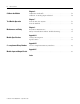
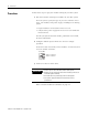
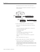
2. Configure module input channels for current or voltage
operation.
Locate the 2-switch assembly on the module’s circuit board, and
set each channel as follows.
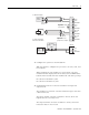
3. Connect I/O devices with cables.
Refer to Install and Wire the Modules on page 11.
IMPORTANT
• Connect only one end of the cable shield to earth ground.
• Channels are not isolated from each other. All analog commons are
connected together internally.
• The module does not provide loop power for analog inputs.
• Use a power supply that matches the transmitter (sensor)
specifications.
12
N
O
Current (ON)
Voltage (OFF)
Switch 1 = Channel 0
Switch 2 = Channel 1