
User Manual Instruction Manual

Publication 1746-UM009B-EN-P - September 2007
Calibrate the Module 63
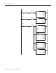
These addresses are used in the example program.
(Each channel requires its own program and separate addresses.)
Compute values required for the calibration program as follows:
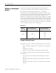
Example Program Addresses
Bit or Value Address
Cal_Lo I:1.0/0 and N10:0/0 (You set these bits in step 3.)
Cal_Hi I:1.0/1 and N10:0/1 (You set these bits in step 4.)
Calibrate I:1.0/2 and N10:0/2 (You set these bits in step 5.)
Convert Enable N10:10/4 (Runtime enable)
Analog_In I:2.0
Lo_Value N10:1
Hi_Value N10:2
Scale_Hi N10:3
Scale_Lo N10:4
Scale_Span N10:7
Span N10:9
Slope_x10K N10:18
Offset N10:21
Analog Scale N10:22
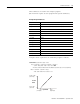
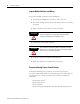
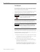
Scaled value = (input value x slope) + offset
Slope = (scaled max. – scaled min.) / (input max. – input min.)
Offset = scaled min. – (input min. x slope)
= (2047 – 409) / (2055 – 400)
1
= 1638 / 1655 = .9897
= 409 – (400 x .9897) = 409 – 395.88 = 13.12
1
The values of 2055 and 400 are from the calibration procedure steps 3 and 4, respectively.
20 mA = 2047
(scale high)
Scaled
Value
Input Value 2055
(High Input)
400
(Low Input)
4 mA = 409
(scale low)