
User Manual Instruction Manual

Publication 1746-UM009B-EN-P - September 2007
62 Calibrate the Module
Calibrate an Analog Input
Channel
We provide an example calibration program and a calibration
procedure to show you how to calibrate an analog input channel.
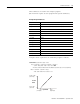
This example assumes an analog output of 4…20 mA from a
transducer. The corresponding decimal code that the module would
write into the processor’s input image table would be 409 at 4 mA and
2047 at 20 mA if the overall error of an input channel were zero.
However, the overall error of ± 0.510% at 20 mA equates to ± 21 LSB
of error, or a code range of 2026…2068. In other words, the value that
the module transfers to the data table for a full scale sensor signal of
20 mA could be any value within the range of 2026…2068. Calibration
should reduce the overall error to less than ± 6 LSB, or a code range
of 2041…2053 for the error of the 20 mA signal.
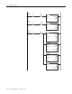
Example Calibration Program
Complete these tasks to maintain calibrated inputs for each channel.
• Add a calibration program for each channel to your application
logic.
• Calibrate each channel.
• Enable the Convert Enable rung (rung 2:4) during runtime.
The calibration program requires three external inputs to calibrate
each channel.
• Lo captures the low calibration value (calibration procedure,
step 3).
• Hi captures the high calibration value (calibration procedure,
step 4).
• Cal scales the Hi and Lo values to provide the slope and offset
(step 5).
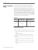
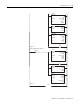
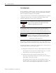
Code Ranges
With this
full-scale
sensor output
For an uncalibrated channel,
the corresponding output
would have this range of error
For a calibrated channel,
the corresponding output
would have this range of error
2068
2053
20 mA > > > > > 2047 > > > > > > > 2047> > >
2041
2026