
User Manual Instruction Manual

Publication 1746-UM009B-EN-P - September 2007
Write Ladder Logic 47
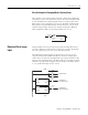
Scale an Analog Output
This example shows the scaling of analog output values to
engineering units for monitoring or controlling purposes.
We are making these assumptions.
• The FIO4I module is located in slot 2 of an SLC 500 system.
• An actuator of a flow control valve is wired to output channel 0.
• The actuator accepts a 4…20 mA signal for a 0…100% of valve
opening.
• The actuator can not receive a signal out of the 4…20 mA range.
• The percentage of valve opening is manually input to the SLC
processor.
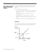
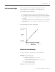
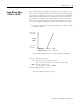
This graph displays the linear relationship.
Calculate the Linear Relationship
Use these equations to compute the scaled output value:
20mA = 31208
(scaled max.)
4mA = 6242
(scaled min.)
Scaled
Value
Input Value
(from data table)
100%
(input max.)
0%
(input min.)
S
ca
l
e
d
va
l
ue =
(i
nput va
l
ue x s
l
ope
)
+ o
ff
set
Slope = (scaled range) / (input range)
Offset = scaled min – (input min x slope)
= (scaled max – scaled min) / (input max – input min)
= 6242 – [0 x (24966 / 100)] = 6242
Scaled value = [input value x 24966 / 100] + 6242
= (31208 – 6242) / (100 – 0) = 24966/100
The slope is greater than 3.2767 so you cannot use SCL instruction.