
User Manual Instruction Manual

Publication 1746-UM009B-EN-P - September 2007
34 Processor and Module Considerations
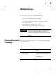
Convert Analog Output Data
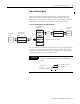
The module converts 16-bit binary values from the output image table
to 14-bit analog output signals and left-justifies the bit code in the
channel word. The output range, decimal representation for the
output range, number of significant bits, and converter resolution are
as shown in the following table.
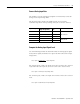
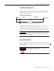
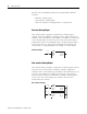
Compute the Analog Output
Use the following formula to compute the output image-table value
(decimal representation) required for a desired analog-output signal
level (to the output device).
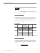
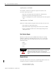
EXAMPLE
For example, if the input image table value is 409 from a 4…20
mA sensor.
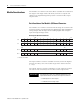
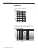
Analog Output Data
Module Output Range Decimal
Representation
(output image table)
Significant
Bits
Resolution
FIO4I 0…21 mA – 1LSB 0…+32,764 13 bits
2.56348 µA/LSB0…20 mA 0…+31,208 12.92 bits
4…20 mA 6242…31,208 12.6 bits
FIO4V –10…+10V dc –
1LSB
–32,768…+32,764 14 bits
1,22070 mV/LSB
0…10V dc – 1LSB 0…32,764 13 bits
0…5V dc 0…16,384 12 bits
1…5V dc 3277…16,384 11.67 bits
Full Scale Input
Full Scale Count
Sensor Signal = x Input Image Value = 0.00977 x 409 = 4 mA
Full-scale Decimal Representation
Full-scale Output
Output Image Value = x Desired Signal Level