
User Manual Instruction Manual

11 Publication 1746-UM009B-EN-P - September 2007
Chapter
2
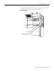
Install and Wire the Modules
This chapter describes procedures to install fast analog I/O modules in
an SLC 500 system. The procedures include the following tasks.
• determine the module’s power requirements
• determine compatibility with other I/O modules
• configure input channels
• select the I/O rack slot
• install the module
• consider when wiring
– using system wiring guidelines
– grounding the cable
– determining cable length
• minimize electrical noise interference
• wire the module
• minimize ground loops
• label the terminal block
Determine the Module’s
Power Requirements
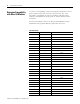
Analog modules require power from the 5V dc and 24V dc backplane
power supplies of the SLC 500 system. This table shows the backplane
power requirements for fast analog I/O modules.
Use this table to compute the module’s portion of total load on the
modular system power supply.
For more information, refer to SLC 500 Systems Selection Guide,
publication 1747-SG001.
Current Load
Catalog Number Current at 5V dc Current at 24V dc
1746-FIO4I 55 mA 150 mA
1746-FIO4V 55 mA 120 mA