
User Manual Instruction Manual

Publication 1746-UM009B-EN-P - September 2007
10 Quick Start
The lowest two bits have no effect on the output value.
Refer to Processor and Module Considerations on page 29 for
more information.
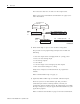
6. Write ladder logic to process the module’s analog data.
We provide several programming examples that include the
following:
• Clear the output when changing mode or cycling power
• Detect an out-of-range input
• Scale analog outputs
• Scale offsets
• Scale and range-check analog inputs and outputs
• PID control with analog I/O scaling
Study these examples to understand how to program the
module.
Refer to Write Ladder Logic on page 39.
7. (Optional) Write ladder logic to maintain calibrated inputs.
We show you how to write ladder logic that provides a
calibrated input reference during runtime, and lets you
periodically calibrate module inputs. We suggest that you modify
the logic examples to suit your application and add them to your
application program.
Refer to Calibrate the Module on page 61 for more information.
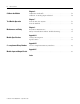
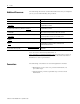
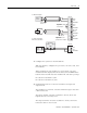
SLC 500 Processor
Data Files
X
(variable input data)msb
Channel 0 Output Word
Channel 1 Output Word
Channel 0 Input Word
Channel 1 Input Word
Input Image
(2 words)
Output Image
(2 words)
Address
I:1.0
I:1.1
Address
O:1.0
O:1.1
lsb
variable output data)msb lsb
X
0000
Bit 15 Bit 11 Bit 0
Bit 15 Bit 2 Bit 0
X = not used