
User Manual


Publication 1746-UM010B-EN-P - April 2001
9-4 Sample Program
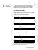
The information for the M1, M0, input image, output image, and the
rotator code is put into one data table. The layout of the file is as
follows:
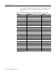
Table 9.C BTM201.rss M1, M0, Input Image, Output Image, and Rotator Code Data Table
Location Description See Page
NXX
(1)
:0
Block header for the M1 configuration file 3-11
NXX:1 thru NXX:100 M1 configuration information 3-13
NXX:101 thru NXX:109 Reserved do not use NA
NXX:110 Block header for the M0 file 4-6
NXX:111 thru NXX:159 M0 file information 3-11, 4-6
NXX:160 thru NXX:175 Input image buffer 6-2
NXX:176 thru NXX:179 Reserved do not use NA
NXX:180 thru NXX:195 Output image table 5-8
NXX:196 thru NXX:199 Reserved do not use NA
NXX:200 thru NXX:203 Current set points NA
NXX:204 thru NXX:207 Current error PV-SP NA
NXX:208 thru NXX:211 Current CVs NA
NXX:212 thru NXX:215 Error codes 8-2
NXX:216 thru NXX:219 CJC temperatures 2-6
NXX:220 thru NXX:223 Firmware revision 9-1
NXX:224 thru NXX:227 P contribution 4-4
NXX:228 thru NXX:231 I contribution 4-4
NXX:232 thru NXX:235 D contribution 4-4
NXX:236 thru NXX:239 Pre-set point NA
NXX:240 thru NXX:243 Wait period NA
NXX:244 thru NXX:247 Reserved for future use NA
NXX:248 thru NXX:255 Reserved do not use NA
(1)
The XX in all data table address above will depend on the data table location of the first BTM and which BTM is being
manipulated by the code.