
User Manual


1 Publication 1746-UM010B-EN-P - April 2001
Chapter
8
Troubleshooting the Module
This chapter provides troubleshooting guidelines.
Troubleshooting with LED
Indicators
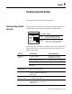
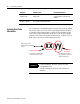
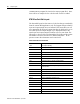
The front panel of the module contains five green LED indicators for
channel status and one green LED indicator for module status.
We present a table of indications, probable causes, and recommended
action. See Table 8.A on page 8-3 and Table 8.B on page 8-4 for a
listing of error codes.
INPUT
ISOLATED
CHANNEL
STATUS
MODULE STATUS
02
13
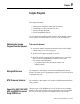
LED: When: Indicates
Channel
Status
On channel is correctly configured
when you enable the channel
Flashing channel fault condition
Module
Status
Flashing communication occurring between
SLC processor and BTM module
On self-check completed OK
Indication Probable Cause Recommended Action:
all indicators
are OFF
no power to module check power to I/O chassis
recycle power as necessary
module performing self–check wait until self check is complete
module performing calibration wait until calibration is complete
possible short on the module
LED failure
replace module
channel status
indicator is ON
channel is correctly configured
when you enable the channel
normal operation
during calibration, the channel is
properly configured for the high–end of
millivolt range
normal calibration
channel status
indicator is flashing
fault condition, such as open circuit or
an under/over range condition
correct fault condition
during calibration, the channel is
properly configured for the low–end of
millivolt range
normal calibration