
User Manual


Publication 1746-UM010B-EN-P - April 2001
6-2 Monitoring Status Data
Values reported in words 12-15 for loops 1–4 vary, depending on the
bit code set in global commands N10:192/bits 08-10 and reported in
input image word N10:168/bits 08-10. You must interpret the reported
value according to the implied decimal point:
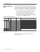
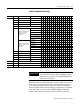
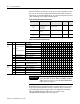
Table 6.C Global Status from All Loops
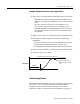
Remember that the module returns the control variable (CV) of each
loop to the input image table as both a numeric value (current CV)
and a time–proportioned output (TPO). For additional information,
Refer to BTM201.rss Data Table Layout on page 9-2 and
BTM50220.RSS Data table layout on page 9-7.
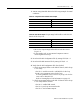
Table 6.B Interpret Implied Decimal Points
If N10:168/10-09-08 Reports: Implied decimal point is: Interpret
:
As:
001
010
101
current setpoint,
current error, or
cold–junction
temperature
1 decimal place
(from the right)
4999 499.9
0 1 1 current CV (analog
output)
2 decimal places 4999 49.99
100
110
error code, or
firmware revision number
none 4999 4999
Word Bit Define Indicated By 1514131211109876543210
8
upper
byte
8-10
Selection of Reported
values
See Important Below
Current setpoint
0 0 1
Current Error value 0 1 0
Current CV (loop output) 0 1 1
Current error code 1 0 0
Cold junction temperature 1 0 1
Firmware revision number 1 1 0
11 Autotune progress 0 = None; 1 = In progress
12 Cold junction low 0 = None; 1 = Alarm
13 Cold junction high 0 = None; 1 = Alarm
14 Reserved
15 Advanced rotator
values
0 = Normal Values
1 = Advanced Diagnostic Values
9
upper
byte
8-11 Reserved
12 M0 download 0 = None; 1 = Download
13 M1 download 0 = None; 1 = Download
14 M0 upload 0 = No; 1 = Upload
15 M1 upload 0 = No; 1 = Upload
IMPORTANT
The sample program returns all six variables. For
their data table locations, Refer to BTM201.rss Data
Table Layout on page 9-2 and BTM50220.RSS Data
table layout on page 9-7.