
User Manual


1 Publication 1746-UM010B-EN-P - April 2001
Chapter
6
Monitoring Status Data
This chapter describes status data reported by the BTM module in the
input image table (16 words), applicable to the sample program.
Input Image Table
Implied Decimal Point
You must interpret the value of displayed 16–bit integer numbers. For
temperature values reported in words 0-3, the implied decimal point is
1 place from the right (for a resolution to be 0.1). For example, if
4999 is displayed, you must interpret it as 499.9.
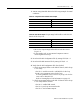
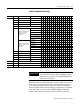
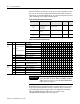
Table 6.A Status Values from Each Loop
12 3 4 Bit Define M1 Indicated By 1514131211109876543210
0123 Current temperature (-3276.8° thru +3276.°7)
4 5 6 7 0 Open circuit 0 = None; 1 =Error
1 Under range 0 = None; 1 =Error
2 Over range 0 = None; 1 =Error
3 Configuration 0 = None; 1 =Valid
4 Parameter value 0 = None; 1 = Error
5 PV rate alarm 10 0 = None; 1 = Alarm
6 Thermal Integrity 16 0 = None; 1 = Alarm
7 High CV limit 2 0 = None; 1 = Alarm
8 Low CV limit 3 0 = None; 1 = Alarm
9 Low temperature 11 0 = None; 1 = Alarm
10 High temperature 12 0 = None; 1 = Alarm
11 Low deviation 13 0 = None; 1 = Alarm
12 High deviation 14 0 = None; 1 = Alarm
>15 Reserved
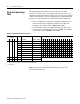
8 9 10 11 0 Loop control 0 = No; 1 = Enabled
1 Loop mode 0 = Manual; 1 = Auto
2 Setpoint 5 0 = Standby; 1 = Run
3 Autotune
complete
0 = No; 1 = Yes
4 Autotune success 0 = No; 1 = Yes
5 Setpoint ramping 0 = No; 1 = Enabled
6 Heat TPO 0 = Off; 1 = On
7 Cool TPO 0 = Off; 1 = On
8-15 See Table 6.C on page 6-2
0 = None; 1 = Alarm
12 13 14 15 Function and value of this word set by N10:192, bits 8-10. See Table 6.B