
User Manual


Publication 1746-UM010B-EN-P - April 2001
Control and Autotune a Loop 5-9
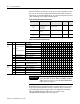
Global Commands to All Loops
Remember that the module returns the control variable (CV) of each
loop to the input image table as both a numeric value (current CV)
and a time–proportioned output (TPO). For additional information,
Refer to BTM201.rss M1, M0, Input Image, Output Image, and Rotator
Code Data Table on page 9-4 and BTM50220.RSS M1, M0, Input
Image, Output Image, and Rotator Code Data Table on page 9-8.
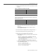
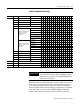
Word Bit To Control Selected By 1514131211109876543210
12 0 Temperature units F =0;C =1
1 Autotune invoke invoke =1;None = 0
2 Autotune abort Abort = 1;None =0
3 Reset error codes None =0; Reset =1
3-7 Reserved
8-10
Selection of Reported value
if bit 11 is not set in the
output image buffer
N10:192/11
Current Setpoint
001
Current Error Value 010
Current CV (loop output) 011
Current Error Code 100
Cold Junction Temperature 101
Firmware Revision Number 110
Selection of Reported value
if bit 11 is set in the output
image buffer
N10:192/11
P Contribution
001
I Contribution 010
D Contribution 011
Pre-set Point 100
Wait Period 101
Reserved 110
11 Advanced Rotator Values Disable = 0;Enable =1
12 MO download request None =0; Download =1
13 M1 download request None =0; Download =1
14 M0 upload request None =0; Upload =1
15 M1 upload request None =0; Upload =1
13 0-15 Reserved
14 0-15 Calibration word
15 0-15 Reserved
IMPORTANT
The sample program returns all six variables. For
their data table locations, Refer to BTM201.rss Data
Table Layout on page 9-2 and BTM50220.RSS Data
table layout on page 9-7.