
User Manual


Publication 1746-UM010B-EN-P - April 2001
5-8 Control and Autotune a Loop
Using the Output Image
Table
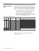
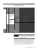
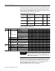
The output image table contains 16 words as shown in Table
5.Cbelow. You must enter a 16–bit signed integer value for the run
temperature setpoint and manual output. If you are using the example
code from the manual you will not manipulate the output image table
directly. You will manipulate the output image buffer N10:180-195.
• For a run temperature setpoint, the implied decimal point is 1
place from the right (causing the resolution to be 0.1). For
example, if you want a value of 499.9, enter 04999.
• For the manual output, the implied decimal point is 2 places
from the right (causing the resolution to be 0.01). For example,
if you want a value of 49.99%, enter 04999.
Note: Refer to Download and Upload Settings on page 9-3 for
download command bits.
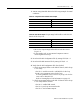
Table 5.C Operating Commands to Loops 1-4
Loops 1-4
Word #
Set a bit or enter a value
12 3 4 bit to Configure Bit Select or Range1514131211109876543210
0 1 2 3 0 loop control Disable=0; Enable=1
X
1 Auto/manual Manual =0; Auto =1
X
2 Setpoint select
Standby=0
(2)
; Run=1
(3)
X
3 Autotune enable Disable=0; Enable=1 X
4
PID integral reset
(1)
Accume = 0;Reset =1 X
5 Ramp enable Disable = 0;Enable =1 X
6 Ramp hold Hold =0; Don’t hold =1 X
7-15 Reserved
4 5 6 7 0-15 Run temp setpoint -3276.7 thru 3276.7
8 9 10 11 0-15 Manual Output -100.00 thru +100.00%
(1)
Requires a 0-to-1 transition for each reset.
(2)
For loops 1-4 standby setpoint is stored in N10:5, 30, 55, 80 respectively.
(3)
Entered below