
User Manual


Publication 1746-UM010B-EN-P - April 2001
Control and Autotune a Loop 5-5
1. Assume using data table N10 in the following example. Set initial
conditions:
• Set to zero Output image buffer table words 188–191 for
loops 1–4.
• In the sample code, it zeros manual outputs to remove
control signals from loops.
2. Download the M1 Configuration File by setting N7:12/00 = 1.
3. Download the M0 Autotune File by setting N7:12/01 = 1.
4. Verify that the M1 Configuration File downloaded:
a. Check input image buffer words 164–167 bits 03, 04 for loops
1–4 to verify:
• bit 03 = 1 module received a valid M1 file for the loop
•bit 04 = 0 no parameter errors for the loop.
If bit 04 (parameter error) is set for any loop, look for the
error code in N10:212–215.
Refer to Locating Error Code Information on page 8-2.
b. Check input image buffer words 168–171 bits 00–02 for loops
1–4 to verify that the module:
• bit 00 = 1 enabled PID control
• bit 01 = 0 put loop into manual mode
• bit 02 = 1 used runtime setpoint
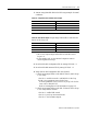
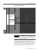
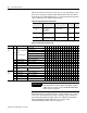
Table 5.A Configuration File N10 Data Table Example
N10:1 bits 00 01 set for PID control
N10:26 bits 00 01 set for PID control
N10:51 bits 00 01 set for PID control
N10:76 bits 00 01 set for PID control
remaining bits/words set for your application
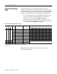
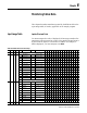
Table 5.B Data Table Example:
Output image buffer table words 180–183
bits 00–03 for loops 1–4.
bit 00 1 enables PID control
bit 01 0 puts loop into manual mode
bit 02 1 uses runtime setpoint
bit 03 1 enables autotune