
User Manual

1 Publication 1746-UM010B-EN-P - April 2001
Chapter
3
Configuring the Module
You configure the module by setting words and bits for each loop in
Configuration Block, N10:0–100, which your ladder logic uses to load
the module’s M1 file. We cover bit selections and word descriptions.
Refer to Table 3.B on page 3-13 for selections, units, and defaults.
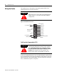
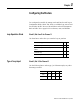
Loop Operation Mode
Word 1, Bits 0 and 1 for Channel 1
Use these bits to select how you want the loop to perform:
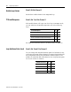
Type of Loop Input
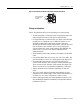
Word 1, Bits 2-5 for Channel 1
Use the following bits to select type J or K thermocouple; any other
bit setting is invalid:
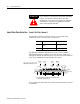
Mode of Loop Operation 01 00
monitor the loop to indicate temperature and alarms 0 0
perform PID loop control with temperature indication and
alarms
01
disable the loop 1 0
invalid setting 1 1
TC 05 04 03 02
type J 0 0 0 0
type K 0 0 0 1