Installation Instructions Barrel Temperature Control Module Cat. No. 1746-BTM Contents Use this document as a guide to install and wire the 1746-BTM barrel temperature control module.
Barrel Temperature Control Module Important User Information Because of the variety of uses for the products described in this publication, those responsible for the application and use of these products must satisfy themselves that all necessary steps have been taken to assure that each application and use meets all performance and safety requirements, including any applicable laws, regulations, codes and standards.
Barrel Temperature Control Module ATTENTION ! 3 Environment and Enclosure This equipment is intended for use in a Pollution Degree 2 industrial environment, in overvoltage Category II applications (as defined in IEC publication 60664-1), at altitudes up to 2000 meters without derating. This equipment is considered Group 1, Class A industrial equipment according to IEC/CISPR Publication 11.
Barrel Temperature Control Module How to Get the Related User Manual The following table describes the related user manual that is available for this module. To order a copy or to view or download an online version, visit The Automation Bookstore at: www.theautomationbookstore.
Barrel Temperature Control Module 5 Install the Module To install your module into the chassis: 1. Turn off the chassis power supply. WARNING ! If you insert or remove the module while backplane power is on, an electrical arc can occur. This could cause an explosion in hazardous location installations. Be sure that power is removed or the area is nonhazardous before proceeding. 2. Align the circuit board of the thermocouple module with the card guides located at the top and bottom of the chassis. 3.
Barrel Temperature Control Module 5. To remove, press the releases at the top and bottom of the module, and slide the module out of the chassis slot.
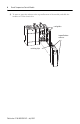
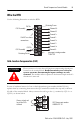
Barrel Temperature Control Module 7 Remove/Install the Removable Terminal Block The module ships with an attached an 18-position removable terminal block (RTB). When you install the module, it is not necessary to remove the RTB. If you ever need to remove it, follow this procedure: 1. Alternately loosen the two retaining screws to avoid cracking the RTB. CJC sensors retaining screws RTB 2. Grasp the RTB at the top and bottom and pull outward and down.
Barrel Temperature Control Module 2. Make certain the color of the RTB mathces the color band on the module. ATTENTION Inserting a wired RTB on an incorrect module can damage the module’s circuitry when power is restored. ! 3. View the write–on label to identify the slot, chassis and module type. SLOT RACK MODULE 4. Align the RTB retaining screws with the mating connector on the module. Be careful not to damage the CJC sensors. CJC sensors retaining screws RTB 5.
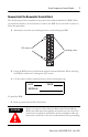
Barrel Temperature Control Module 9 Wire the RTB Use the following illustration to wire the RTB: Retaining Screw CJC A+ CJC Assembly Channel 0+ CJC A- Channel 0Channel 1+ Channel 1- Do NOT use these connections Channel 2+ Channel 2Channel 3+ CJC B+ CJC Assembly CJC BRetaining Screw n/c Channel 3spare part catalog number: 1746-RT32 Cold Junction Compensation (CJC) ATTENTION ! Do not remove or loosen the cold junction compensating thermistors located on the terminal block.
Barrel Temperature Control Module Wiring Guidelines Follow these guidelines when planning your system wiring. • To limit the pickup of electrical noise, keep thermocouple and millivolt signal wires away from power and load lines. • For high immunity to electrical noise, use Alpha 5121 (shielded, twisted pair) or equivalent wire for millivolt sensors; or use shielded, twisted pair thermocouple extension lead wire specified by the thermocouple manufacturer.
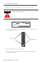
Barrel Temperature Control Module 11 Preparing and Wiring the Cables To prepare and connect cable leads and drain wires, follow these steps: Remove the foil shield and drain wire from sensor-end of the cable Signal Wires Extract the drain wire but remove the foil shield, at the module-end of the cable. Drain Wire Signal Wires 1. At each end of the cable, strip some casing to expose individual wires. 2. Trim signal wires to 5–inch lengths beyond the cable casing. Strip about 3/16 inch (4.
Barrel Temperature Control Module 7. At the source-end of cables from mV devices (see following figure): • remove the drain wire and foil shield • apply shrink wrap as an option • connect to mV devices keeping the leads short Make unshielded wires as short as possible. Solder drain wires to braid at casing. Wires 3/8 Signal Wires Connect I/O chassis bolt to earth ground 3/8 Chnl 0 Chnl 1 Chnl 2 Cables Make unshielded wires as short as possible. IMPORTANT Limit braid length to 12” or less.
Barrel Temperature Control Module 13 The following information applies when operating this equipment in hazardous locations: Informations sur l’utilisation de cet équipement en environnements dangereux : Products marked “CL I, DIV 2, GP A, B, C, D” are suitable for use in Class I Division 2 Groups A, B, C, D, Hazardous Locations and nonhazardous locations only. Each product is supplied with markings on the rating nameplate indicating the hazardous location temperature code.
Barrel Temperature Control Module Specifications Module Location SLC chassis - any I/O module slot except 0 Input from System Backplane 5Vdc @ 0.110 A, 24Vdc @ 0.
Barrel Temperature Control Module 15 Notes: Publication 1746-IN020B-EN-P - July 2002
Rockwell Automation Support Rockwell Automation provides technical information on the Web to assist you in using its products. At http://support.rockwellautomation.com, you can find technical manuals, a knowledge base of FAQs, technical and application notes, sample code and links to software service packs, and a MySupport feature that you can customize to make the best use of these tools.