
Installation Instructions Owner's manual


Blow-molding Module 33
Publication 1746-IN014B-EN-P - January 2001
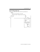
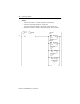
Input Image
Notes: Error flag value (decimal) -1 = axis control structure address of parameter in error. For additional control structure
information, see page 30.
For description definitions, see page 43.
Addresses for axes 1-4
axis 1 axis 2 axis 3 axis 4 Status-bit Description (=1 for reported status)
0/0 2/0 4/0 6/0 profile enable is set for duration of profile
0/1 2/1 4/1 6/1 follows state of hold-value-0 control bit
0/2 2/2 4/2 6/2 follows state of hold-value-1 control bit
0/3 2/3 4/3 6/3 follows state of hold-value-2 control bit
0/4 2/4 4/4 6/4 verifies completion of structure download
0/5 2/5 4/5 6/5 verifies completion of structure upload
0/6 2/6 4/6 6/6 verifies zero-scale calibration has been recorded
0/7 2/7 4/7 6/7 verifies full-scale calibration has been recorded
0/8 2/8 4/8 6/8 verifies completion of setpoint profile download
0/9 2/9 4/9 6/9 verifies completion of process-variable profile upload
0/10 2/10 4/10 6/10 verifies completion of master setpoint profile download
0/11 2/11 4/11 6/11 verifies completion of interpolated setpoint profile upload
0/12 2/12 4/12 6/12 indicates state of sync input logically ANDed with profile enable bit
0/13 2/13 4/13 6/13 indicates state of synch output
0/14 2/14 4/14 6/14 follows state of parison-weight control bit
0/15 2/15 4/15 6/15 follows state of parison-velocity control bit
1 3 5 7 error flag (see note)
8 9 10 11 current profile step
12 13 14 15 current setpoint
16 17 18 19 current process variable
20 21 22 23 current control variable
24 25 26 27 current dac output
28 29 30 31 current adc input