
Installation Instructions Owner's manual


32 Blow-molding Module
Publication 1746-IN014B-EN-P - January 2001
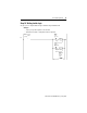
Output Image
Note: For description definitions, see page 43.
Addresses for axes 1-4
axis 1 axis 2 axis 3 axis 4 Control-bit Description (1 = enable)
0/0 2/0 4/0 6/0 profile-enable
0/1 2/1 4/1 6/1 hold-value-0
0/2 2/2 4/2 6/2 hold-value-1
0/3 2/3 4/3 6/3 hold-value-2
0/4 2/4 4/4 6/4 download axis control structure (from SLC)
0/5 2/5 4/5 6/5 upload axis control structure (to SLC)
0/6 2/6 4/6 6/6 record current axis position as zero-scale calibration
0/7 2/7 4/7 6/7 record current axis position as full-scale calibration
0/8 2/8 4/8 6/8 download setpoint profile (from SLC)
0/9 2/9 4/9 6/9 upload process-variable profile (to SLC)
0/10 2/10 4/10 6/10 download master setpoint profile (from SLC)
0/11 2/11 4/11 6/11 upload interpolated setpoint profile (to SLC)
0/12 2/12 4/12 6/12 synch input
0/13 2/13 4/13 6/13 synch output
0/14 2/14 4/14 6/14 parison weight control
0/15 2/15 4/15 6/15 accumulator velocity control
1 3 5 7 reserved
8 11 14 17 hold-value “0”
9 12 15 18 hold-value “1”
10 13 16 19 hold-value “2”
20 high speed analog input word (see page 12)
21 – 31 reserved