
Installation Instructions Owner's manual

Blow-molding Module 29
Publication 1746-IN014B-EN-P - January 2001
Using M0/M1 Files
The module’s M0 file receives axis-control structures and axis profiles from your
designated N files. The module returns to designated N files:
• axis-control structures for verification
• process-variable profiles to indicate how setpoint profiles were executed
Your ladder logic must move this data between N files and M0/M1 files.
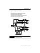
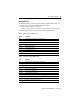
M0 file - write blocks to the BLM module
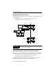
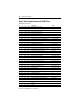
M1 file - read blocks from the BLM module
Words Description
0-63 Control structure for axis 1 (see next page for listing)
64-127 Control structure for axis 2
128-191 Control structure for axis 3
192-255 Control structure for axis 4
256-511 Setpoint profile for axis 1
512-767 Setpoint profile for axis 2
768-1023 Setpoint profile for axis 3
1024-1279 Setpoint profile for axis 4
1280-1535 Master Setpoint profile
Words Description
0-63 Control structure for axis 1 (see next page for listing)
64-127 Control structure for axis 2
128-191 Control structure for axis 3
192-255 Control structure for axis 4
256-511 Process-variable profile for axis 1
512-767 Process-variable profile for axis 2
768-1023 Process-variable profile for axis 3
1024-1279 Process-variable profile for axis 4
1280-1535 Interpolated setpoint profile
1536 Module’s firmware revision (in BCD)
Note: M1 control structure files are returned in engineering units.