
Installation Instructions Owner's manual

Blow-molding Module 21
Publication 1746-IN014B-EN-P - January 2001
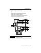
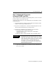
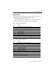
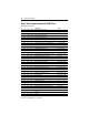
Wiring a Two-head Dual-actuator Machine
This setup has two identical injection units. Wire axis 1 and 2 identical to axis 3 and
4 with these I/O devices:
• analog output to the valve amplifier for the accumulator
• LVDT position input from the accumulator
• analog output to the valve amplifier for the parison die head
• LVDT position input from the parison die head
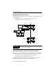
IMPORTANT
If multiple power sources can be used, do not exceed the
specified isolation voltage.
Proportional
Valve and
Cylinder
Position
Transducer
Valve
Amp
Proportional
Valve and
Cylinder
Position
Transducer
Valve
Amp
24
23
34
33
26
25
30
29
38
37
36
35
32
31
28
27
Axis 2
Axis 1
Axis 4
Axis 3
same wiring
as Axis 2
same wiring
as Axis 1