Installation Instructions Blow-molding Module (catalog number 1746-BLM) Before you begin Use this document as a guide to installing and powering-up your Blow-molding Module. We assume that you are already familiar with the SLC 500™ family of Small Logic Controllers and associated I/O modules. Tools that you need • 1/8” slotted screwdriver Handling the Module Take these precautions to guard against ESD damage: ATTENTION ! Electrostatic discharge can damage the module.
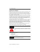
Blow-molding Module Important User Information Because of the variety of uses for the products described in this publication, those responsible for the application and use of this control equipment must satisfy themselves that all necessary steps have been taken to assure that each application and use meets all performance and safety requirements, including any applicable laws, regulations, codes and standards.
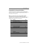
Blow-molding Module 3 Recommendation for using associated software To program the SLC processor to interface the module with molding machine operation, your PC should be equipped with programming software RSLogix 500™ from Rockwell Software. For instructions on using the software, refer to the documentation that accompanied it.
Blow-molding Module Step: 1 Module description We cover these aspects of module description: • • • • • • • features overview communication with SLC processor internal microprocessor internal PID control algorithm analog I/O digital I/O Features This 4-axis position-control module has these features: • Open-loop or closed-loop control • Independent and coordinated axis control • Position- and time-based control • Accumulator push-out control • Zero-scale/full-scale (offset & span) calibration for posit
Blow-molding Module 5 Overview The module performs its servo control task independently, but is dependent on the SLC processor for all of its configuration and run-time information. The processor may be also be used to supply process data or timing information over the backplane in certain situations (e.g. parison drop synchronization on continuous extrusion machines, or accumulator position in reciprocating screw machines).
Blow-molding Module Communication with the SLC Processor • • • • • • shared memory control bit/status bit handshake micro processor PID control algorithm digital I/O analog I/O Shared memory From the ladder programmer’s perspective, communication with the module is via five data files located in shared memory on the module: Config(G) File contains information regarding the operational mode and feature settings of the module.
Blow-molding Module 7 M0 File contains four axis control structures and five setpoint profiles. Each axis has a variety of PID and profiling options, controlled by its axis control structure. Each axis also has a unique 256-point setpoint profile. A single master setpoint profile is used with an “interpolate” command to ease the task of generating setpoint profiles. Entries in the M0 File are written by move or copy instructions in ladder program.
Blow-molding Module Module’s microprocessor The module processor is a 16-bit fixed-point digital signal processor (DSP). It communicates with the analog I/O channels over a high speed (2MHz) full-duplex synchronous serial link. Serial connection between the processor and analog I/O hardware facilitates electrical isolation. Digital I/O is performed in a similar fashion. The module processor manages all communications between the module and the SLC processor.
Blow-molding Module 9 Step: 2 Machine applications of the module Each module can control up to four axes of closed-loop position control on most types of blow-molding machines. Configurations include: • accumulator push-out control and three parison axes • two accumulator push-outs and two parison axes You can use multiple modules on machines with more than four heads.
Blow-molding Module Control of Accumulator Head Machines The module controls parison wall thickness on accumulator machines by following a setpoint profile of wall thickness vs. accumulator ram position. In this configuration, the module is capable of controlling up to three blow molding heads. One analog I/O channel is used for accumulator ram velocity control while the others are used for mandrel position control. Optionally the module may simply monitor ram position.
Blow-molding Module 11 Control of Continuous Extrusion Machines The module controls parison wall thickness on continuous extrusion machines by following a setpoint profile of wall thickness vs. time. The module is capable of controlling up to four blow molding heads in this mode. Each of the module’s four analog I/O channels is used for mandrel position control. Mandrel position is a function of the elapsed time since the last synchronization signal, indicating start of parison drop.
Blow-molding Module Control of Reciprocating Screw Machines Reciprocating screw machines have multiple heads and a single accumulator. Control of accumulator position is performed by the SLC processor. The module may be used to monitor the accumulator (screw) position in either of two ways on this type of machine: • with an analog input to the module: Each module configured in this manner can control three heads. This method offers optimal performance.
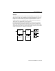
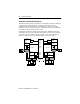
Blow-molding Module Proportional Valve and Cylinder Position Transducer ram Servo Valve and Valve Hydraulic Amp Cylinder LVDT mandrel 13 Valve Amp Single accumulator controlled by separate analog module and SLC ladder logic.
Blow-molding Module Step: 3 Module operation with an accumulator machine Position-based Operation In position-based mode, setpoint profiles are specified as a function of the position of a second, independent axis position. Here the independent axis corresponds to the accumulator ram position, while the dependent axis corresponds to mandrel position (or ram velocity). Conceptually, the shot size of the independent axis is divided into 256 segments.
Blow-molding Module 15 Monitoring Mandrel Position Instantaneous mandrel position may be monitored by reading the current process variable from the module’s input file. Several other values of interest are also available for each axis (e.g. control output, profile step, etc.). Process variable profiles may be read from the module’s M1 file. Controlling Ram Velocity Accumulator ram velocity is controlled in position-based mode by specifying ram velocity as a function of ram position.
Blow-molding Module Operation with an Auxiliary Position Input This mode of operation lets you control four machine heads per 1746-BLM. Your ladder program is responsible for calibration and scaling of process variable data sent to the module via the output file. A value of -32768 corresponds to the fully-forward ram position and +32767 corresponds to the at-shotsize ram position. See page 12 for additional information on controlling with a separate, high-speed analog module.
Blow-molding Module 17 Controlling Mandrel Position Static Control: Mandrel position may be controlled statically with three axis-hold values and corresponding hold-value control bits accessible via the module output file. Hold values are prioritized with hold value #0 being highest, and hold value #2 being lowest. In time-based mode the hold values have no special interpretation. In absence of an active profile, the highest priority enabled hold value becomes the position setpoint.
Blow-molding Module Step: 5 Determining an axis setpoint All position setpoints and process variables are represented in the SLC500 16-bit signed integer format, where the minimum value of -32768 corresponds to zero-scale (fully-closed or fully-forward) and the maximum value of +32767 corresponds to full-scale (fully-open or fully-retracted). The setpoint for a machine axis comes from one of four prioritized sources: an active profile or one of three hold values.
Blow-molding Module 19 Step: 6 Wiring the module WARNING ! When you insert or remove the module while the backplane power is on, or you connect or disconnect the RTB with field side power applied, an electrical arc can occur. This could cause an explosion in hazardous location installations. Be sure that power is removed or the area is nonhazardous before proceeding. Repeated electrical arcing causes wear to contacts on both the module and its mating connector.
Blow-molding Module Description Axis 1 Axis 2 Axis 3 Axis 4 Reserved System 4, 3, 2, 1 Digital OUT- 17 13 9 5 Digital OUT+ (+24EXT) 18 14 10 6 Digital IN- 19 15 11 7 Digital IN+ 20 16 12 8 -24V dc RET 21 +24V dc EXT 22 Analog OUT- (GND) 23 27 31 35 Analog OUT+ 24 28 32 36 Analog IN- 25 29 33 37 Analog IN+ 26 30 34 38 Excitation- (-10V) 39 Excitation+ (+10V) 40 Publication 1746-IN014B-EN-P - January 2001
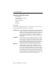
Blow-molding Module 21 Wiring a Two-head Dual-actuator Machine This setup has two identical injection units.
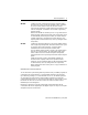
Blow-molding Module Wiring a Continuous-extrusion Machine This setup has four identical injection units.
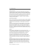
Blow-molding Module 23 Wiring Digital I/O To use module hardware inputs (DIN) for start-of-drop synchronization, reset bit 05 = 0 of the G-file axis-configuration word, and wire as follows: (Channel 1 shown. See page 27 for G-file configuration.) 14 + digital output sync output - 13 + 24V EXT 16 + - 15 22 21 digital input start-of-drop trigger dc common + 24V dc supply - IMPORTANT If multiple power sources can be used, do not exceed the specified isolation voltage.
Blow-molding Module Minimizing interference from radiated electrical noise: • Isolate signal wiring (such as LVDT input cables) from power lines and sources of electrical noise (such as motors and proportional amplifiers). • Use shielded twisted pairs for all input and output connections. • Make cables and unshielded leads as short as possible. • Connect the shields of LVDT input cables and drive-output cables to earth ground at the I/O chassis at the nearest chassis mounting bolt.
Blow-molding Module 25 Step: 7 Configuring the SLC processor (including I/O, M0/M1, and G file) This procedure is based on RSLogix500 programming software, version 2.0 or later. For other software, the procedure may vary. Configure the SLC processor, I/O, size of M0/M1 files, and G file offline to match your system layout. 1. With the File pull-down window, open the ladder file associated with this project, or create a project (ladder file) for it. 2.
Blow-molding Module 4. Select the Adv Configuration icon and launch it. Then select/enter: a. Length of M0 file at 1536 words, M1 file at 1537 (listed in section 7). b. Length of G file at 5 words. 5. Select and launch the Enter G Data icon. a. Change the display radix to hex. You see: 0 2020 0 0 0 0 b. Select word one (as shown) and enter the bit-selected data word that corresponds to axis 1. You determine the equivalent hex value of this word in next section.
Blow-molding Module 27 G-file Configuration The module requires software-configured selections in G file words 1-4 for axes 1-4, respectively.
Blow-molding Module You may set bits by entering an equivalent bit-set word in hex. For example, a hex value of 0062 represents: 0062 axis profile size of 256 setpoints (bits 15-08 = 256 = 00) axis synch input and output controlled by SLC (bits 07-04 = 0 1 1 0 = 6) accumulator driven by independent position-based axis 0 (bits 03-00 = 0 0 1 0 = 2) IMPORTANT Before operating the module for the first time, you must download the G file to the module.
Blow-molding Module 29 Using M0/M1 Files The module’s M0 file receives axis-control structures and axis profiles from your designated N files. The module returns to designated N files: • axis-control structures for verification • process-variable profiles to indicate how setpoint profiles were executed Your ladder logic must move this data between N files and M0/M1 files.
Blow-molding Module Step: 8 Axis Control Structures in M0/M1 Files Addresses for Axes1, 2, 3 and 4(1) 1 2 0/0 64/0 128/0 192/0 enable PID Proportional term 0/1 64/1 128/1 192/1 enable PID Integral term 0/2 64/2 128/2 192/2 enable PID Derivative term 0/3 64/3 128/3 192/3 enable reverse-acting output 0/4 64/4 128/4 192/4 enable reverse sensing input : : : reserved 1 65 129 193 KC (proportional gain x 100) for 0 ≤ gain ≤ 256 1 ≤ KC ≤ 25600 2 66 130 194 KCB (proport
Blow-molding Module (1) 31 To save space, 1K = 1000, -32K = -32768, +32K = +32767 when needed. Refer to Descriptions of module parameters on page 43 . M1 control structure files are returned in engineering units.
Blow-molding Module Output Image Addresses for axes 1-4 axis 1 axis 2 axis 3 axis 4 Control-bit Description (1 = enable) 0/0 2/0 4/0 6/0 profile-enable 0/1 2/1 4/1 6/1 hold-value-0 0/2 2/2 4/2 6/2 hold-value-1 0/3 2/3 4/3 6/3 hold-value-2 0/4 2/4 4/4 6/4 download axis control structure (from SLC) 0/5 2/5 4/5 6/5 upload axis control structure (to SLC) 0/6 2/6 4/6 6/6 record current axis position as zero-scale calibration 0/7 2/7 4/7 6/7 record current axis pos
Blow-molding Module 33 Input Image Addresses for axes 1-4 axis 1 axis 2 axis 3 axis 4 Status-bit Description (=1 for reported status) 0/0 2/0 4/0 6/0 profile enable is set for duration of profile 0/1 2/1 4/1 6/1 follows state of hold-value-0 control bit 0/2 2/2 4/2 6/2 follows state of hold-value-1 control bit 0/3 2/3 4/3 6/3 follows state of hold-value-2 control bit 0/4 2/4 4/4 6/4 verifies completion of structure download 0/5 2/5 4/5 6/5 verifies completion of structure uplo
Blow-molding Module Using Timing Diagrams Study these timing diagrams for position-based and time-based modes of operation. Figure 1 Example Diagrams for Position-based Model (see wiring on page 23) Velocity-controlled Ram Axis 2 profile enable O:e.2/0 Axis 2 profile status I:e.2/0 (1) (2) shot size (4) Axis 2 position (3) zero scale Position-controlled Mandrel Axis 1 profile enable O:e.0/0 Axis 1 profile status I:e.
Blow-molding Module 35 Step: 10 Writing Ladder Logic We give you two sample ladder rungs to illustrate using handshake bits. • Rung 0 – copies your profile setpoints to the module – instructs the module to interpolate between setpoints ax1 ax0 download setpoint profile and enable profiling B3:0 0000 1 Master Setpoint Profile (pts. 0-127) COP Copy File Source #N7:0 Dest #M0:1.1280 Length 128 Master Setpoint Profile (pts. 128-255) COP Copy File Source #N7:128 Dest #M0:1.
Blow-molding Module • Rung 1 – waits for the module to confirm completion of interpolation – copies the interpolated profile into a buffer file – copies the interpolated profile to the module’s axis-1 profile area – instructs the module to read the interpolated profile (from its M1 file) ax ch10 download master setpoint profile status I:1 ax 1 ax0 download setpoint profile and enable profiling B3:0 10 OTHER 1 0001 Scratch Buffer Pts. 0-127 ax 1 0 Head COP Copy File Source #M1:1.
Blow-molding Module 37 Step: 11 Calibrating the module To achieve precise closed-loop position control, you must calibrate the module’s analog inputs. The module uses calibration data to transform setpoints/process variables to/from 16-bit signed integer format to the corresponding voltages present at the analog inputs.
Blow-molding Module Step: 12 Tuning a PID Loop Use the following standard PID tuning method to tune the module’s PID control loops: Introduction In the module’s feedback control system, steady-state error using the proportional term is 100% x 1/(1+K), where K = proportional gain. EXAMPLE If the proportional gain is 9, the steady state error is an unacceptably high 10%. At the maximum proportional gain of 256, the error is better at 0.4%, but such a high gain may cause instability.
Blow-molding Module 39 Step: 13 Troubleshooting The module and SLC provide three aids for troubleshooting: • one status LED on the module • axis error flags returned from the module in the input image table • SLC processor’s fault indication in the status file When the module or SLC processor detects these types of errors or faults, it responds accordingly, and you must clear the error or fault as follows: When indicated by: This type of error or fault: may be cleared by module status LED major fault
Blow-molding Module Axis error flags The SLC operating system makes no response to out-of-range errors that you may make when entering parameters in axis-control structures (M0 file). But when the module detects that you downloaded an out-of-range parameter, it returns a status code to indicate the word number in the axis- control structure containing the error. The status code is returned in input image table words 1, 3, 5, and 7, the error flag words for axes 1, 2, 3, and 4.
Blow-molding Module 41 Specifications Analog Inputs Analog Outputs Exicitation Output Digital Input Conversion Rate 10KHz Resolution 14 bits Differential Input Range +/-10Vdc Common Mode Input Range +/-200Vdc Differential Impedance 800KΩ Common Mode Impedance 400KΩ Isolation from PLC backplane Tested to 500Vdc for 60 sec or equivalent Overvoltage Protection +/-500V Input Conductors: Wire size Belden 8761 or equivalent 22-14 AWG stranded copper wire 3/64 inch insulation maximum Wire Ca
Blow-molding Module Digital Output Environmental (1) Type Open Collector Maximum OFF State Voltage 30Vdc Isolation from PLC backplane Tested to 500Vdc for 60 sec or equivalent Output Conductors: Wire size Belden 8761 or equivalent 22-14 AWG stranded maximum 3/64 inch insulation maximum Wire Category 2(2) Power requirement 5 Watts (1A @ +5Vdc) Operating (ambient) temperature 0 to 60°C Storage temperature -40 to +85°C Relative humidity 5 to 95% (non-condensation) Agency Certifications W
Blow-molding Module 43 Descriptions of module parameters Module Parameter Description axis control structure 64 axis-configuration words that you enter in the M0 file axis current adc input raw 14-bit value read from adc (for LVDT position counts) axis current control output 16-bit integer axis current dac output raw 14-bit value written to dac axis current process variable 16-bit integer representing the position input axis current profile step indicates which step of a profile is currently
Blow-molding Module European Communities (EC) Directive Compliance If this product has the CE mark it is approved for installation within the European Union and EEA regions. It has been designed and tested to meet the following directives.
Blow-molding Module 45 Rockwell Automation Support Rockwell Automation offers support services worldwide, with over 75 sales/support offices, over 500 authorized distributors, and 260 authorized systems integrators located throughout the United States alone, plus Rockwell Automation representatives in every major country around the world.
Blow-molding Module Hazardous Location Approval The following information applies when operating this equipment in hazardous locations: Products marked “CL I, DIV 2, GP A, B, C, D” are suitable for use in Class I Division 2 Groups A, B, C, D, Hazardous Locations and nonhazardous locations only. Each product is supplied with markings on the rating nameplate indicating the hazardous location temperature code.
Blow-molding Module 47 Allen-Bradley is a trademark of Rockwell Automation Logix500 is a trademark of Rockwell Software SLC 500 is a trademark of Rockwell Automation Publication 1746-IN014B-EN-P - January 2001
Publication 1746-IN014B-EN-P - January 2001 Supersedes Publication 1746-5.14 - November 1999 PN 957464-71 © 2001 Rockwell International Corporation. Printed in the U.S.A.