
Manual


Publication 1746-UM004B-EN-P - December 2005
A-2 Specifications
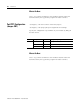
IMPORTANT
If a Hand-held Terminal, Data Table Access Module,
or interface converter is connected to the link
coupler, the additional backplane power draw of
these components must be added to the 0.125 A
listed in the table above. This only applies when the
module is connected to the network via the link
coupler and 1747-C10 cable or 1747-C11 cable. This
does not apply when the 1747-C13 cable is used.
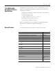
Component Operating Voltage Current Requirement
Hand-held Terminal 24V dc 0.105 A
Data Table Access Module 24V dc 0.104 A
Interface Converter 24V dc 0.060 A
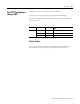
IMPORTANT
The BASIC module receives its power from the SLC
backplane. The power consumption of the module
must be taken into consideration when planning
your SLC 500 system. Refer to the documentation
supplied with your SLC 500 fixed or modular
controller for additional information on power
supplies and current requirements.
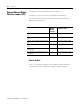
IMPORTANT
Port DH485 is not isolated.
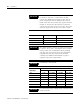
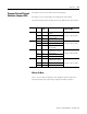
Communication Distance Allowed in m (ft)
Rate (Kbps) RS-232 RS-423 RS-422 RS-485
300 15 (50) 1230 (4000) 1230 (4000) 1230 (4000)
600 15 (50) 920 (3000) 1230 (4000) 1230 (4000)
1200 15 (50) 770 (2500) 1230 (4000) 1230 (4000)
4800 15 (50) 245 (800) 1230 (4000) 1230 (4000)
9600 15 (50) 120 (400) 1230 (4000) 1230 (4000)
19200 15 (50) 60 (200) 1230 (4000) 1230 (4000)
IMPORTANT
Use the RS-423 jumper settings when communicating
in RS-232 mode.