
Manual

Publication 1746-UM004B-EN-P - December 2005
Programming Overview 4-15
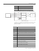
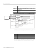
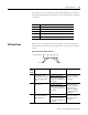
Figure 4.3 Data Flow Between the SLC Processor and Port PRT2 of the Module
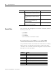
In addition, the commands in the following table provide status of and
control over the data transfer between the SLC processor and port
PRT2 of the module.
CALL 118 Allows unsolicited writes from a remote SLC or PLC node.
CALL 122 Reads a PLC data file and transfers it to the SLC I/O or M files.
CALL 123 Transfers data from the SLC I/O or M files to a remote PLC.
Command Purpose
SLC Processor
CALL 123
CALL 23
CALL 22
CALL 122
CALL 118
PRINT#
INPUT#
INPL#
INPS#
GET#
PRT2 OUTPUT QUEUE
PRT2 INPUT QUEUE
256 bytes
256 bytes
Port PRT2
1746-BAS or 1746-BAS-T Module
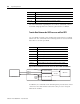
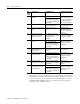
Command Purpose
MODE Sets the port parameters of PRT1, PRT2, and DH485.
CALL 16 Enables interrupt capability when a DF1 packet is received.
CALL 17 Disables the DF1 packet interrupt capability.
CALL 30 Sets the port parameters for PRT2.
CALL 31 Displays the current PRT2 port configuration on the program port terminal
screen.
CALL 35 Retrieves the current character in the 256 character input buffer of port PRT2.
CALL 36 Retrieves the number of characters in the input or output buffer of port PRT2.
CALL 37 Clears the peripheral port input and/or output buffers.
CALL 97 Enables the DTR signal for port PRT2.
CALL 98 Disables the DTR signal for port PRT2.
CALL 108 Enables DF1 driver communications. You must use this CALL in conjunction
with CALLs 16, 17, 118, 122, and 123.
CALL 110 Prints the complete output buffer with addresses, front pointer, and number of
characters in the buffer to the console device.
CALL 111 Prints the complete input buffer with addresses, front pointer, and number of
characters in the buffer to the console device.
CALL 113 Disables DF1 driver communications.