
Manual

Publication 1746-UM004B-EN-P - December 2005
3-14 Install and Wire Your Module
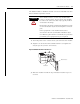
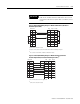
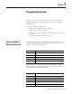
Figure 3.12 RS-422 Wiring Diagram
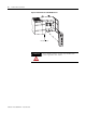
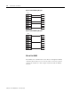
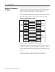
Figure 3.13 RS-485 Wiring Diagram
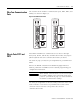
Wire to Port DH485
Port DH485 can communicate to user devices through the DH485
communication mode. Use a 1747-C10 cable or 1747-C13 cable to
connect the module to a link coupler interfaced with the DH485
network.
TXD1
RXD2
3
4
COM5
RXD+6
7
8
TXD+9
RXD
TXD
COM
TXD+
RXD+
Basic
TRXD-1
2
3
4
COM5
6
7
8
TRXD+9
TRXD-
COM
TRXD+
Basic