
Manual

Publication 1746-UM004B-EN-P - December 2005
Install and Wire Your Module 3-11
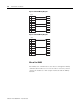
DTE and DCE Overview
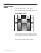
DTE - Data Terminal Equipment
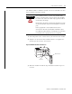
The module’s serial ports are configured as 9-pin Data Terminal
Equipment (DTE), as are most terminals or computer ports.
IMPORTANT
You need to know whether the device connecting to
the module has a DTE or DCE interface.
Figure 3.9 through Figure 3.13 are provided to help
you make the appropriate connection.
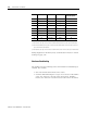
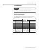
DTE 9 Pinout Signal from
DTE
Perspective
DTE 25 Pinout
Pin # Signal Description Pin # Signal Description
1 NC-No Connection
(for BASIC module only)
Input 8 CD-Carrier Detect
2 RXD-Received Data Input 3
3 TXD-Transmitted Data Output 2
4 DTR-Data Terminal Ready Output 20
5 Com-Signal Common Shared 7
6 DSR-Data Set Ready Input 6
7 RTS-Request to Send Output 4
8 CTS-Clear to Send Input 5
9 NC-No Connection
(for BASIC module only)
Input 22 RI-Ring Indicator