
Manual

Publication 1746-UM004B-EN-P - December 2005
3-10 Install and Wire Your Module
(1)
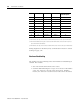
In RS-423 mode, these pins are still connected to their RS-422 loads. Do not use these pins in RS-423 mode.
(2)
In RS-422 and RS-485 modes these pins are connected to their RS-423 drivers and receivers. Do not use these
pins in either RS-422 or RS-485 mode.
(3)
In RS-485 mode, these pins are still connected to their RS-422 receivers. Do not use these pins in RS-485 mode.
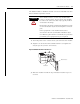
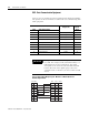
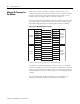
Wiring diagrams for the RS-232/423 communication mode are shown
starting on page 3-12.
Hardware Handshaking
The module uses the following rules when hardware handshaking is
enabled. The module:
• does not transmit until CTS becomes active.
• examines DSR following the receipt of a character. If the DSR is
active, the character is placed in the input queue. If DSR is
inactive, the character is assumed to be noise and is discarded.
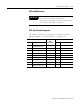
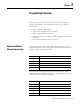
Pin RS-232/423 RS-422 RS-485 IBM AT Standard
RS-232 Signals
1 Note 1 422 TXD - TRXD - DCD or CD
2 RXD 422 RXD - (3) RXD
3 TXD (2) (2) TXD
4 DTR (2) (2) DTR
5 COMMON COMMON COMMON COMMON
6 DSR 422 RXD + (3) DSR
7 RTS (2) (2) RTS
8 CTS (2) (2) CTS
9 (1) 422 TXD + TRXD + RI