SLC 500 BASIC and BASIC-T Modules Catalog Numbers 1746-BAS and 1746-BAS-T User Manual
Important User Information Solid state equipment has operational characteristics differing from those of electromechanical equipment. Safety Guidelines for the Application, Installation and Maintenance of Solid State Controls, publication SGI-1.1, available from your local Rockwell Automation sales office or online at http://www.literature.rockwellautomation.com), describes some important differences between solid state equipment and hard-wired electromechanical devices.
Summary of Changes The information below summarizes the changes to this manual since the last printing. To help you find new and updated information in this release of the manual, we have included change bars as shown to the right of this paragraph.
2 Summary of Changes Notes: Publication 1746-UM004B-EN-P - December 2005
Table of Contents Preface Who Should Use This Manual . . . Purpose of This Manual. . . . . . . . Related Documentation . . . . . How to Use This Manual . . . . . . . Terms and Abbreviations. . . . . . . Conventions Used in This Manual . . . . . . . . . . . . . . . . . . . . . . . . . . . . . . . . . . . . . . . . . . . . . . . . . . . . . . . . . . . . . . . . . . . . . . . . . . . . . . . . . . . . . . . . . . . . . . . . . . . . . . . . . . . . . . . . . .
ii Table of Contents Chapter 4 Programming Overview Understand Module Memory Organization . . . . . . . . . . . . . Allocate SLC memory for the Module . . . . . . . . . . . . . . . . . Module ID Codes. . . . . . . . . . . . . . . . . . . . . . . . . . . . . BASIC Programming Instructions . . . . . . . . . . . . . . . . . . . . BASIC Commands . . . . . . . . . . . . . . . . . . . . . . . . . . . . BASIC Statements. . . . . . . . . . . . . . . . . . . . . . . . . . . . . BASIC Operators . . . . . . . . . .
Table of Contents iii Appendix C Lithium Battery Replacement, Handling, and Disposal Battery Replacement . Battery Handling . . . . Storage . . . . . . . . Transportation . . . Battery Disposal . . . . . . . . . . . . . . . . . . . . . . . . . . . . . . . . . . . . . . . . . . . . . . . . . . . . . . . . . . . . . . . . . . . . . . . . . . . . . . . . . . . . . . . . . . . . . . . . . . . . . . . . . . . . . . . . . . . . . . . . . . . . . . . . . . . . . . . . . . . . . . . .
iv Table of Contents Publication 1746-UM004B-EN-P - December 2005
Preface Read this preface to familiarize yourself with the rest of the manual. This preface covers the following topics. • • • • • Who Should Use This Manual Who should use this manual The purpose of this manual How to use this manual Terms and abbreviations Conventions used in this manual Use this manual if you are responsible for designing, installing, programming, or troubleshooting control systems that use SLC 500 programmable controllers.
2 Preface Related Documentation The following documents contain additional information regarding Rockwell Automation products. For Read Publication Number A BASIC language reference manual that describes BASIC commands, CALLS, and functions BASIC Language Reference Manual 1746-RM001 A programming manual with detailed instructions on installing and using BASIC development software to program the BASIC and BASIC-T module.
Preface Terms and Abbreviations 3 The following terms and abbreviations are specific to this product. For a complete listing of Allen-Bradley terminology, refer to the Allen-Bradley Industrial Automation Glossary, publication ICCG-7.1.
4 Preface Publication 1746-UM004B-EN-P - December 2005
Chapter 1 Module and Development Software Overview This chapter introduces you to the SLC 500 BASIC and BASIC-T modules and the BASIC development software. After reading this chapter you should be familiar with the: • • • • • Overview module components and features. BASIC development software features. typical configurations of the module. module hardware specifications. module-related products. The module and the development software provide the following benefits.
1-2 Module and Development Software Overview BASIC and BASIC-T Modules The modules are single-slot modules that reside in a SLC 500 fixed or modular controller chassis. Use the module as: • a foreign device interface. • an operator interface. Figure 1.1 Module with Door Open BASIC BASIC-T 5 4 3 2 1 9 8 7 6 5 4 3 2 1 PR T1 5 4 3 2 1 9 8 7 6 PR T1 9 8 7 6 5 4 3 2 1 9 8 7 6 PR T2 PR T2 DH485 DH485 Hardware Features The module provides the following hardware features.
Module and Development Software Overview 1-3 Software Features The module provides the following software features.
1-4 Module and Development Software Overview Module LED Indicators There are eight LED indicators on the front of the module. These LED indicators are used for module diagnostics and operator interface. Figure 1.2 Module LEDs BASIC ACT 485 FAULT BA LOW PR T1 LED1 PR T2 LED2 LED Color Status Indication ACT Green ON The module is receiving power from the backplane and is executing BASIC code. Blinking The module is in Command mode. OFF The module is not receiving power from the backplane.
Module and Development Software Overview BASIC Development Software (1747-PBASE) 1-5 The BASIC development software provides the user with a structured and efficient means to create BASIC programs for the module. This software is loaded into a an MS-DOS compatible personal computer. It uses the personal computer to facilitate editing, compiling (translating), uploading, and downloading of BASIC programs.
1-6 Module and Development Software Overview Typical Configurations The typical configuration of the SLC system that incorporates your BASIC or BASIC-T module depends on whether the module is: • integrated with a SLC 500 fixed or modular controller. • programmed directly with an ASCII terminal or programmed using a personal computer with the BASIC development software, 1747-PBASE. • communicating with a DH485 network or with an external source through a modem using DF1 protocol.
Module and Development Software Overview 1-7 Figure 1.3 Typical Configurations SLC 500 Fixed Controller Power Supply Slot Filler BASIC or BASIC-T Module SLC 500 Input BASIC Output Modular Module or Module Processor BASIC-T Module Module Programming Interface Your module can be programmed using an ASCII terminal with ASCII terminal emulation software. You can also use a personal computer with the BASIC development software (catalog number 1747-PBASE).
1-8 Module and Development Software Overview ASCII Terminal Interface Use an ASCII terminal to enter a BASIC program one line at a time to your module through port PRT1. The ASCII terminal connected to the module must be an industrial terminal, workstation, or personal computer (without the BASIC development software) that communicates in alphanumeric mode. An ASCII terminal can also be used to display charts or graphs generated by the BASIC program. Figure 1.4 shows a typical ASCII terminal interface.
Module and Development Software Overview 1-9 Figure 1.5 BASIC Development Software Interface (RS-232) Null Modem Cable Personal Computer with BASIC Development Software SLC 500 Controller with BASIC or BASIC-T Module In this configuration, the serial port on the personal computer is connected to port PRT1 on the module. The personal computer communicates with the module through terminal emulation over an RS-232 interface. Port PRT1 must be configured as the program port.
1-10 Module and Development Software Overview The 1747-PIC interface/converter converts the RS-232 signals from the personal computer RS-232 serial port to RS-485 format. IMPORTANT When using the BASIC development software to interface with port DH485 of the module, PBASE must be configured for DH485 communication through the configuration and terminal selection menus. Refer to the BASIC Development Software Programming Manual, publication 1746-PM001, for additional information.
Module and Development Software Overview 1-11 Figure 1.7 DH485 Network Configuration SLC 500 Controller 1747-C11 Cable DH485 Communication Cable (Belden #9842) SLC 500 Controller with BASIC or BASIC-T Module 1747-C11 Cable Personal Computer with BASIC Development Software 1747-C10 Cable Interface/Converter RS-232 to RS-485 Catalog Number 1747-PIC The 1747-PIC interface/converter converts the RS-232 signals from the personal computer RS-232 serial port to RS-485 format.
1-12 Module and Development Software Overview Figure 1.8 shows the module using DF1 to control communications with a modem. In this configuration, the module is interfaced with a DH485 network through a peer-to-peer communication interface with full-duplex, DF1 protocol. Figure 1.
Module and Development Software Overview 1-13 power from the processor to the link coupler. (The 1747-C10 cable and 1747-C11 cable are interchangeable.) IMPORTANT By configuring JW4 for DF1 communication on PRT2, DH485 communications are disabled.
1-14 Module and Development Software Overview Publication 1746-UM004B-EN-P - December 2005
Chapter 2 Component Selection After reading this chapter, you should understand the: • module memory requirements for BASIC programming and be able to select the memory modules necessary for your application. • concepts of connecting your module to the DH485 network and be able to select the components necessary for your application. • concepts of connecting a modem to the module and be able to select the necessary components for your application.
2-2 Component Selection Optional Memory Module The optional memory module provides nonvolatile storage of user BASIC programs and port configuration. The socket that holds the optional memory module is located on the module’s mother board as shown in Figure 2.1. Figure 2.1 Optional Memory Module Socket Location CAT FRN SER SLC 500 BASIC MODULE SERIAL NO.
Component Selection 2-3 Your module can program the 1747-M1, 1747-M2, 1771-DBMEM1, and 1771-DBMEM2 EEPROM optional memory modules. Jumper JW3 is used to redirect the module circuitry for the different memory module options. Refer to Chapter 3 of this manual for additional information on jumper JW3. IMPORTANT The module can program and erase EEPROM memory modules. However, it cannot program or erase UVPROM memory modules. The data format of the module EEPROM optional memory module is hexadecimal.
2-4 Component Selection Figure 2.
Component Selection 2-5 Figure 2.3 1747-C13 Cable Connection DH485 Communication Cable (Belden 9842) Link Coupler 1747-AIC SLC 500 Controller with BASIC or BASIC-T Module 1747-C10 Cable 1747-C13 Cable The 1747-C10 cable supplies power to the 1747-AIC. The 1747-C13 cable acts only as a communication link and does not carry 24V dc power. The 24V dc can come from either the processor or an outside power source. The 1747-C10 or 1747-C11 cable carries 24V dc power from the processor to the link coupler.
2-6 Component Selection computer with the BASIC development software to the module across a DH485 network. IMPORTANT DH485 Cable Requirements When using the BASIC development software to interface with the module through the 1747-PIC, the BASIC development software must be configured for DH485 communication through the configuration and terminal selection menus. Refer to the BASIC Development Software Programming Manual, publication 1746-PM001, for additional information.
Component Selection 2-7 Figure 2.
2-8 Component Selection Leased Phone Line A leased phone line is a private, dedicated phone line. Leased phone lines provide a phone link between modems that is available for communication at all times. Typically, leased phone lines are used when you have a high or constant transfer of communication between the module and external devices. Radio Link A radio link provides a communication link when phone lines are inaccessible or expensive to use.
Chapter 3 Install and Wire Your Module After reading this chapter, you should: • set the module’s jumpers. • install your module into your SLC 500 fixed or modular controller system. • wire the mating connectors of the cables used to interface user devices to the module ports. Set Module Jumpers The module has four sets of jumpers that you need to set. Jumpers JW1 and JW2 configure ports PRT1 and PRT2. Jumper JW3 configures the type of optional memory module. Jumper JW4 configures the program port.
3-2 Install and Wire Your Module ATTENTION Do not expose the module to surfaces or other areas that may typically hold an electrostatic charge. Electrostatic charges can alter or destroy memory. Set Jumper JW1 Use jumper JW1 to select one of the following configurations for port PRT1. • RS-232/423 • RS-422 • RS-485 Figure 3.
Install and Wire Your Module 3-3 Use the worksheet in Appendix B to document the selected jumper setting of jumper JW1. Documenting your selection provides others with information necessary to integrate the module with their SLC 500 fixed or modular controllers. Set Jumper JW2 Use jumper JW2 to select one of the following configurations for port PRT2. • RS-232/423 • RS-422 • RS-485 Figure 3.
3-4 Install and Wire Your Module Set Jumper JW3 Use jumper JW3 to configure the memory module socket for one of the following optional memory modules. • • • • • • 1747-M1, 8 KB EEPROM (1746-BAS module only) 1747-M2, 32 KB EEPROM (1746-BAS module only) 1747-M3, 8 KB UVPROM (1746-BAS module only) 1747-M4, 32 KB UVPROM (1746-BAS module only) 1771-DBMEM1, 8 KB EEPROM (1746-BAS-T module only) 1771-DBMEM2, 32 KB EEPROM (1746-BAS-T module only) Figure 3.
Install and Wire Your Module 3-5 Use the worksheet in Appendix B to document the selected jumper setting of jumper JW3. Set Jumper JW4 Use jumper JW4 to select one of the following configurations for the module ports.
3-6 Install and Wire Your Module IMPORTANT ATTENTION IMPORTANT The first setting shown in Figure 3.5 is the default configuration. When the jumper is set in this position, the module always powers up in Command mode at 1200 KB, no parity, 8 data bits, and 1 stop bit. All other jumper settings for JW4 are illegal and may cause damage to the module. When DF1 protocol is selected for port PRT2, port DH485 is not available for DH485 programming or runtime operation.
Install and Wire Your Module 3-7 The BASIC module or BASIC-T module can also be installed in an SLC fixed controller expansion chassis. ATTENTION Never install, remove, or wire any module while power is applied. Also, do not expose the modules to surfaces or other areas that may typically hold an electrostatic discharge. Electrostatic discharge can damage integrated circuits or semiconductors if you touch backplane connector pins.
3-8 Install and Wire Your Module Figure 3.7 Installation in a SLC 500 I/O Chassis SLC 500 Processor ATTENTION Publication 1746-UM004B-EN-P - December 2005 Never install, remove, or wire any module with power applied to the chassis.
Install and Wire Your Module Wire Your Communication Ports 3-9 The locations of the module’s communication ports, PRT1, PRT2, and DH485, are shown in Figure 3.8. Figure 3.8 Communication Ports BASIC BASIC-T 5 4 3 2 1 9 8 7 6 5 4 3 2 1 PR T1 5 4 3 2 1 Wire to Ports PRT1 and PRT2 9 8 7 6 PR T1 9 8 7 6 5 4 3 2 1 9 8 7 6 PR T2 PR T2 DH485 DH485 Ports PRT1 and PRT2 can communicate to user devices through RS-232/423, RS-422, and RS-485 communication modes.
3-10 Install and Wire Your Module Pin RS-232/423 RS-422 RS-485 IBM AT Standard RS-232 Signals 1 Note 1 422 TXD - TRXD - DCD or CD 2 RXD 422 RXD - (3) RXD 3 TXD (2) (2) TXD 4 DTR (2) (2) DTR 5 COMMON COMMON COMMON COMMON 6 DSR 422 RXD + (3) DSR 7 RTS (2) (2) RTS 8 CTS (2) (2) CTS 9 (1) 422 TXD + TRXD + RI (1) In RS-423 mode, these pins are still connected to their RS-422 loads. Do not use these pins in RS-423 mode.
Install and Wire Your Module 3-11 DTE and DCE Overview IMPORTANT You need to know whether the device connecting to the module has a DTE or DCE interface. Figure 3.9 through Figure 3.13 are provided to help you make the appropriate connection. DTE - Data Terminal Equipment The module’s serial ports are configured as 9-pin Data Terminal Equipment (DTE), as are most terminals or computer ports.
3-12 Install and Wire Your Module DCE - Data Communication Equipment Devices such as modems are Data Communication Equipment (DCE). The pinouts on these terminals are defined for ease of interfacing with DTE equipment.
Install and Wire Your Module IMPORTANT 3-13 For DCE devices other than modems, connect the DSR of the module with the DSR of the device. The CD signal of the device (other than a modem) is not used. Figure 3.10 RS-232/423 Wiring Diagram - Module to DTE Device (Hardware Handshaking Disabled) Basic DTE (2) (2) DTE DCD (3) 1 N.C. 2 RXD TXD 3 TXD RSD 4 DTR DSR 5 COM COM 6 DSR DTR 7 8 RTS CTS CTS RTS 9 N.C.
3-14 Install and Wire Your Module Figure 3.12 RS-422 Wiring Diagram Basic 1 TXD 2 RXD RXD TXD 3 4 5 COM 6 RXD+ COM TXD+ TXD+ RXD+ 7 8 9 Figure 3.13 RS-485 Wiring Diagram Basic 1 TRXD- TRXD- 2 3 4 5 COM COM 6 7 8 9 TRXD+ TRXD+ Wire to Port DH485 Port DH485 can communicate to user devices through the DH485 communication mode. Use a 1747-C10 cable or 1747-C13 cable to connect the module to a link coupler interfaced with the DH485 network.
Chapter 4 Programming Overview This chapter provides an overview of the information needed to program your module. After reading this chapter, you should be familiar with: • • • • module memory organization. SLC memory allocation for your module. BASIC programming instructions. entering, running, and editing a BASIC program from an ASCII terminal. • interfacing the module with other devices.
4-2 Programming Overview Allocate SLC memory for the Module Your SLC 500 fixed or modular controller communicates to the module through the SLC backplane interface. The backplane interface transfers data from the CPU input and output image tables to the module input and output buffers as shown in Figure 4.1. For more information regarding the transfer of data between the SLC controller and the module, refer to page 4-16 of this manual and to the BASIC Language Reference Manual, publication 1747-RM001.
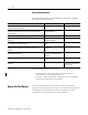
Programming Overview 4-3 Figure 4.2 SLC 5/02 Controller to Module M0 and M1 File Transfer Word 0 Word 100 Word 1 . Word 101 . . . . . Word 62 Word 162 Word 63 Word 163 Word 0 Word 100 Word 1 . Word 101 . . . . . Word 62 Word 162 Word 63 Word 163 CPU M0 File CPU M1 File BASIC or BASIC-T Module Input Buffer BASIC or BASIC-T Module Output Buffer Module ID Codes The following table lists the ID codes needed to configure the memory of your SLC 500 fixed or modular controller.
4-4 Programming Overview BASIC Commands BASIC commands are programming instructions that are executed during the Command mode except for CONTROL-C. CONTROL-C takes you from Run mode to Command mode. Typically these commands are used to perform some type of program maintenance. The following table lists the BASIC programming commands. Command Function Examples CONT CONTinue program execution after a STOP statement or CONTROL-C command.
Programming Overview 4-5 Refer to the BASIC Language Reference Manual, publication 1747-RM001, for additional information on these commands. BASIC Statements BASIC statements are programming instructions that are executed during Run mode. Typically these statements are used to control program execution. The following table lists the BASIC programming statements. Statement Function Examples CLEAR CLEAR variables, interrupts, and strings. CLEAR CLEAR (S&I) CLEAR stacks and interrupts.
4-6 Programming Overview Statement Function Examples RETI RETURN from interrupt. RETI RETURN RETURN from subroutine. RETURN ST@ Store top of stack at user specified location. ST@ 1000H, ST@ A STOP Break program execution. STOP STRING Allocate memory for STRINGs. STRING 50, 10 Refer to the BASIC Language Reference Manual, publication 1747-RM001, for additional information on these statements. BASIC Operators BASIC operators are programming instructions that are executed during Run mode.
Programming Overview Operator Function Examples ( ) .OR. ( ) Combine the first expression with the second expression using .OR.. 2.OR.1 ( ) .XOR. ( ) Combine the first expression with the second expression using .XOR.. 3.XOR.2 MTOP Return last valid memory address. PRINT MTOP ()*() Multiply expressions together. 4*4 p Store constant. 3.1415926 RND Return a random number. RND SGN ( ) Return the sign of argument. SGN (-5) SIN ( ) Return the sine of argument. SIN (3.
4-8 Programming Overview Create and Edit a BASIC Program Module execution is controlled through a BASIC program residing in RAM or ROM. You have the option of creating and editing this program. • on a personal computer using the BASIC development software and then downloading it to the module. BASIC development software uses an MS-DOS compatible personal computer to facilitate editing, compiling (translating), uploading, and downloading BASIC programs.
Programming Overview 4-9 2. Connect the ASCII terminal to the selected program port on the module. 3. Verify that the console device is configured to communicate with the module (protocol and communication settings). 4. Apply power to your system. If there is no program in RAM, this appears on the ASCII terminal. SLC 500 BASIC Module - Catalog Number 1746-BAS Firmware release: 1.
4-10 Programming Overview 5. Enter a line of the BASIC program at the system prompt [>]. READY >10 REM FIRST PROGRAM >20 PRINT “HELLO WORLD” A BASIC program line always begins with a line number and must contain at least one character, but no more than 68 characters. 6. Press [RETURN] to end the program line. Run a BASIC Program After entering your BASIC program, you are ready to run it. To run a BASIC program, type RUN at the system prompt [>].
Programming Overview 4-11 Stop a BASIC Program To stop a program that is running, press IMPORTANT [Ctrl–C]. If [Ctrl–C] is disabled, you cannot stop program execution through a BASIC command. You must have jumper JW4 set in the default position and cycle power to stop program execution. Edit a BASIC Program Line Through an ASCII Terminal When the module is in Command mode, you can edit the BASIC program that resides in RAM. Editing a BASIC program is done on a line-by-line basis.
4-12 Programming Overview Operation Use To Key Strokes Move Provide right/left cursor control. [Space bar] - moves the cursor one space to the right. [Backspace] - moves the cursor one space to the left. Replace Replace the character at the current cursor position. Press the key that corresponds to the character that will replace the character at the current cursor position. Insert Insert text at the current cursor position.
Programming Overview 4-13 Delete a BASIC Program Line When the module is in Command mode, you can delete an existing line of the BASIC program. To delete an existing line of the BASIC program, type the line number of the line to delete; then press [RETURN] as shown on the following screen: READY >10 Renumber a BASIC Program When the module is in Command mode, you can renumber the BASIC program that resides in RAM. To renumber a BASIC program, you must enter a REN command at the system prompt [>].
4-14 Programming Overview Command Renumbers the Program Starting at Key Strokes Renumber The beginning of the program. The new line numbers begin at 10 and increment by 10. [REN] The beginning of the program. The new line numbers begin at 10 and increment by NUM. [REN[NUM]] The beginning of the program. The new line numbers begin with NUM1 and increment by NUM2. [REN[NUM1],[NUM2]] NUM2. The new line numbers begin with NUM1 and increment by NUM3.
Programming Overview Command Purpose CALL 118 Allows unsolicited writes from a remote SLC or PLC node. CALL 122 Reads a PLC data file and transfers it to the SLC I/O or M files. CALL 123 Transfers data from the SLC I/O or M files to a remote PLC. 4-15 Figure 4.
4-16 Programming Overview Command Purpose CALL 114 Initiates DF1 packet transmission. CALL 115 Checks DF1 packet transmission status. CALL 117 Gets DF1 packet length. CALL 119 Resets port parameters back to their default settings. For more information regarding the use of these commands, refer to the BASIC Language Reference Manual, publication 1747-RM001. Transfer Data Between the SLC Processor and Port PRT1 Use port PRT1 to interface the module with external devices sending ASCII code.
Programming Overview 4-17 Command Purpose MODE Sets the port parameters of PRT1, PRT2, and DH485. CALL 94 Displays the current port PRT1 configuration on the program port terminal screen. CALL 95 Retrieves the number of characters in the input or output buffer of port PRT1. CALL 96 Clears port PRT1 input and output buffers. CALL 103 Prints the complete output buffer with addresses, front pointer, and number of characters in the buffer to the program port screen.
4-18 Programming Overview Command Purpose CALL 91 Transfers words 0...39 of the module output buffer to a remote DH485 data file. CALL 92 Transfers the data from a remote DH485 interface file to words 0...39 of the module input buffer. CALL 93 Transfers words 0...39 of the module output buffer to a remote DH485 interface file. CALL 118 Allows unsolicited writes from a remote SLC or PLC node. Figure 4.
Programming Overview 4-19 Transfer Data Between the SLC Processor and the Module Use the module to interface with the SLC processor. For example, the module performs large mathematical calculations for the processor that the SLC processor uses to execute an operation. The commands in the following table are used to transfer data either to or from the SLC processor. Command Purpose CALL 14 Converts 16-bit signed integer located in the BASIC input buffer to BASIC floating-point.
4-20 Programming Overview Figure 4.6 Data Flow Between the Module and SLC Processor CALL 14/15 BASIC INPUT BUFFER CALL 53 CALL 56 CALL 24/25 BASIC OUTPUT BUFFER SLC OUTPUT IMAGE 16 bytes 16 bytes CALL 54 SLC M0 CALL 57 SLC M1 SLC INPUT IMAGE 128 bytes 128 bytes SLC Processor 1746-BAS or 1746-BAS-T Module In addition, the commands in the following table provide status of and control over the data transfer between the SLC processor and module.
Programming Overview 4-21 The SLC processor and module operate independently of each other. The following CALLs allow the SLC processor and module to interrupt each other. SLC Fault Codes CALL Purpose CALL 16 Enables interrupt capability when a DF1 packet is received. CALL 17 Disables the DF1 packet interrupt capability. CALL 20 Enables SLC processor interrupt capability. CALL 21 Disables SLC processor interrupt capability. CALL 26 Generates an interrupt to the SLC processor.
4-22 Programming Overview SLC Fault Code 5AH Description Possible Cause Recommended Action Hardware interrupt problem. Module hardware problem. Module internal stacks, pointers (if XBY instructions are used) are corrupted by the user program. Module is trying to be configured using G files. Wrong M0/M1 file size is chosen. Verify that the module slot is enabled. Cycle power to the module to re-initialize parameters and re-run the program. 5BH G file configuration error.
Appendix A Specifications Module Hardware Specifications The module hardware specifications are listed in the following tables. Specification Value Power Supply Loading at 5V dc 0.150 A (module only) Power Supply Loading at 24V dc 0.070 A (module only) 0.150 A (module with link coupler) 0.125 A (module with link coupler)(2) Noise Immunity NEMA Standard ICS 2-230 Vibration Displacement: 0.015 in., peak-to-peak at 5...57 Hz Acceleration: 2.5 g at 57...
A-2 Specifications IMPORTANT If a Hand-held Terminal, Data Table Access Module, or interface converter is connected to the link coupler, the additional backplane power draw of these components must be added to the 0.125 A listed in the table above. This only applies when the module is connected to the network via the link coupler and 1747-C10 cable or 1747-C11 cable. This does not apply when the 1747-C13 cable is used. Component Operating Voltage Current Requirement Hand-held Terminal 24V dc 0.
Specifications 1747-PBASE BASIC Development Software Specifications A-3 The BASIC development software must be loaded into a personal computer to operate. This personal computer must conform to the following specifications. • IBM PC/AT compatible computer with display and keyboard • DOS version 3.1 to 6.22 • 640 KB of RAM memory • 1 floppy disk drive (3 1/2 in. or 5 1/4 in.
A-4 Specifications Publication 1746-UM004B-EN-P - December 2005
B Appendix Worksheets This appendix contains important information you should be concerned with when configuring the module. The information is general in nature and supplements specific information contained in earlier chapters of this manual. Topics include worksheets for configuring: • the BASIC or BASIC-T module. • jumpers JW1-JW4. Module Configuration Specify the connection information by filling in the boxes in the figure below. Figure B.
B-2 Worksheets What to Do Next Give a copy of this worksheet to the hardware installer. Store this worksheet with your application program for future reference. Port PRT1 Configuration (Jumper JW1) See Figure 3.1 for the locations of the four jumpers. See Figure 3.2 for jumper JW1 pin assignments and settings. Specify the configuration of port PRT1 on your module by filling in the table below.
Worksheets Port PRT2 Configuration (Jumper JW2) B-3 See Figure 3.1 for the locations of the four jumpers. See Figure 3.3 for jumper JW2 pin assignments and settings. Specify the configuration of port PRT2 on your module by filling in the table below.
B-4 Worksheets Optional Memory Module Selection (Jumper JW3) See Figure 3.1 for the locations of the four jumpers. See Figure 3.4 for jumper JW3 pin assignments and settings. Specify the optional memory module selection for the system by filling in the table below.
Worksheets Program Port and Protocol Selection (Jumper JW4) B-5 See Figure 3.1 for the locations of the four jumpers. See Figure 3.5 for jumper JW4 pin assignments and settings. Specify the Program Port and its protocol by filling in the table below.
B-6 Worksheets Publication 1746-UM004B-EN-P - December 2005
Appendix C Lithium Battery Replacement, Handling, and Disposal This appendix contains important information you should know when using lithium batteries. Battery Replacement Your module provides back-up power for RAM through a replaceable lithium battery (catalog number 1747-BA). This battery provides back-up for approximately five years. A BAT LOW indicator on the front of the module alerts you when the battery voltage has fallen below the replace battery threshold level.
C-2 Lithium Battery Replacement, Handling, and Disposal Figure C.1 Battery Location CAT FRN SER SLC 500 BASIC MODULE SERIAL NO. 54 3 2 1 CONFIG 9 87 6 54 3 2 1 DF1 9 87 6 DH485 Red Wire White Wire Battery 3. Unplug the battery connector. IMPORTANT The module has a capacitor that provides 30 minutes of battery back-up while the battery is disconnected. Data in RAM is not lost if the battery is replaced within 30 minutes. 4. Remove the battery from the retaining clips. 5.
Lithium Battery Replacement, Handling, and Disposal Battery Handling C-3 The procedures listed below must be followed to be sure of proper battery operation and reduce personnel hazards. • Use battery only for intended operation • Do not ship or dispose of cells except according to recommended procedures • Do not ship on passenger aircraft ATTENTION Do not charge the batteries. An explosion could result or the cells could overheat causing burns.
C-4 Lithium Battery Replacement, Handling, and Disposal Three or More Batteries Procedures for the transportation of three or more batteries shipped together within the United States are specified by the Department of Transportation (DOT) in the Code of Federal Regulations, CRF49, “Transportation”. An exemption to these regulations, DOT – E7052, covers the transport of certain hazardous materials classified as flammable solids.
Lithium Battery Replacement, Handling, and Disposal Battery Disposal C-5 The following procedures must be followed when disposing of lithium batteries. ATTENTION Do not incinerate or dispose of lithium batteries in general trash collection. Explosion or violent rupture is possible. Batteries should be collected for disposal in a manner to prevent against short circuiting, compacting, or destruction of case integrity and hermetic seal.
C-6 Lithium Battery Replacement, Handling, and Disposal Publication 1746-UM004B-EN-P - December 2005
Index Numerics 1746-BAS BASIC Module 1-2, 2-4 1746-BAS-T BASIC-T Module 1-2, 2-4 1747-AIC Isolated Link Coupler 1-10, 2-3, 2-4, 2-5 1747-C10 Cable 1-13, 2-5, 2-6 1747-C11 Cable 1-10, 1-13, 2-5 1747-C13 Cable 1-13, 2-4 1747-KE DH-485/RS-232C Communication Interface Module 2-3 1747-M1 8 KB EEPROM 2-2, 3-4 1747-M2 32 KB EEPROM 2-2, 3-4 1747-M3 8 KB UVPROM 3-4 1747-M4 32 KB UVPROM 3-4 1747-PBASE BASIC Development Software 1-5 1747-PIC Interface/Converter 1-9, 1-11, 2-3, 2-5 1771-DBMEM1 8 KB EEPROM 2-2, 3-4 17
2 Index DH485 network cable requirements 2-6 interfacing with the module and development software 1-3, 2-3 dial-up modem for DF1 communication 2-6 DTE 3-11 E editing a program line 4-11 EEPROM 2-2, 3-4 entering a program 4-8 H hardware features 1-2 hardware handshaking 3-10 I input/output buffer address map 4-20 installation and wiring communication ports 3-9 DH485 communication port 3-5, 3-14, 4-17 fixed controller expansion rack 3-6 modular controller rack 3-6 overview 3-1 PRT1 communication port
Index creating and editing 4-8 data transfer between the SLC and BASIC module 4-2, 4-19 deleting a program line 4-13 editing a program line 4-11 entering a program 4-8 instructions 4-3 memory requirements 2-1 module ID codes 4-3 module input buffer addresses 4-1 module output buffer addresses 4-1 operators 4-6 overview 4-1 renumbering a program 4-13 running a program 4-10 statements 4-5 stopping a program 4-11 programming instructions 4-3 programming operators 4-6 programming statements 4-5 PRT1 communicat
Rockwell Automation Support Rockwell Automation provides technical information on the web to assist you in using its products. At http://support.rockwellautomation.com, you can find technical manuals, a knowledge base of FAQs, technical and application notes, sample code and links to software service packs, and a MySupport feature that you can customize to make the best use of these tools.