
Owner's manual


Publication 1746-RM001A-US-P
12-30 Output Functions
The second input argument is the decimal node address of the PLC remote device
(0 through 254). If the number is not within this range, the status equals 2 and the
write message does not occur.
The third input argument is the file number to be written to on the PLC remote
device (0 through 255). If the number is not within this range, the status equals 2
and the write message does not occur. The parameter is PUSHed, but ignored, if
the common interface file is chosen in the first parameter.
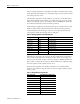
The fourth input argument is the destination file type on the remote device. This
number is ignored if the common interface file is chosen in the first parameter
(assumes integer file). If the file type code is not one of these shown below, the
status equals 2 and the write message does not take place.
The fifth input argument is the starting word offset within the file on the PLC-2
remote device (0 through 32766). For PLC-3 integer, binary, or status files, the
value is 0-9999 (decimal). For PLC-3 I/O files, the value is 0-4095 (decimal). For
PLC-3 timer or counter files the value is 0. If the number is not within this range,
the status equals 2 and the transfer does not occur.
The sixth input argument is the number of elements to be transferred. If the
number is not within the range shown below, the status equals 2 and the transfer
does not occur.
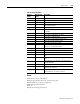
Table 12.9 File Type Written to the Remote Device
File Type File Type Code Words/Element (1 word = 16 bits)
Integer File ASC(N) 1 word/element
Status File ASC(S) 1 word/element
Counter File ASC(C) 3 words/element
Timer File ASC(T) 3 words/element
Bit File ASC(B) 1 word/element
Control File ASC(R) 3 words/element
Input File ASC(I) 1 word/element
Output File ASC(O) 1 word/element
Table 12.10 Valid Element Length Range
File Type Code Valid Element Length Range
ASC(N) 1 to 64
ASC(S) 1 to 64
ASC(C) 1 to 21
ASC(T) 1 to 21
ASC(B) 1 to 64
ASC(R) 1 to 21
ASC(I) 1 to 64
ASC(O) 1 to 64
Common Interface File 1 to 64