
Assembly Connections for POINT I/O and ArmorPOINT I/O EtherNet/IP Adapters User Manual
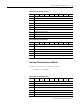
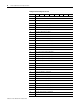
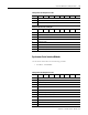
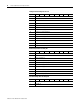
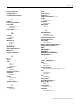
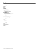
Table Of Contents
- 1734-UM016A-EN-P Assembly Connections for POINT I/O and ArmorPOINT I/O EtherNet/IP Adapters User Manual
- Important User Information
- Table of Contents
- Preface
- Chapter 1 - Introduction
- Chapter 2 - Configuration
- Chapter 3 - Using an Assembly Connection
- Chapter 4 - Assembly Structure
- Chapter 5 - 1734/1738 I/O Module Assembly Information
- Module Assembly Information
- Module Specific Details
- Two-channel Discrete Input Modules
- Four-channel Discrete Input Modules
- Eight-channel Discrete Input Modules
- Two-channel Discrete Output Modules with Status
- Two-channel Discrete Output Modules
- Four-channel Discrete Output Modules with Status
- Four-channel Discrete Output Modules
- Eight-channel Discrete Output Modules with Status
- Eight-channel Discrete Output Modules
- Four-channel Discrete Diagnostic Input Modules
- Two-channel Relay and AC Output Modules
- Four-channel Relay and AC Output Modules
- Sixteen-channel Discrete Diagnostic Input Modules
- Sixteen-channel Discrete Output Modules
- Eight-channel Configurable Discrete Input/Output Modules
- Very High Speed Counter Modules
- Counter Modules
- Two-channel Analog Input Modules
- Four-channel Analog Input Modules
- Eight-channel Analog Input Modules
- Two-channel Analog Output Modules
- Four-channel Analog Output Modules
- Two-channel RTD Input Modules
- Two-channel Thermocouple Input Modules
- Synchronous Serial Interface Modules
- Address Reserve Module
- ASCII Interface Modules
- Index
- Back Cover
Publication 1734-UM016A-EN-P - October 2010
70 1734/1738 I/O Module Assembly Information
The format and length of the Produced and Consumed I/O assemblies vary
with the configuration of the module. For more information regarding the
specific fields of these assemblies and how they are impacted by the
configuration, refer to the product user manual.
15 ASCII Consume String Data Type
16 ASCII Transmit Swap Mode
17 Transmit Handshake Mode
Produced Input Data Assembly 101
Byte Bit 7Bit 6Bit 5Bit 4Bit 3Bit 2Bit 1Bit 0
0 RX Transaction ID
1 Status
2
Reserved or Length
(2)
(2)
The meaning of these fields depends on the configuration of the module.
3
Reserved or Length
(2)
4 ASCII Data (from 1 to 128 bytes)
N
(1)
(1)
The length of the assembly depends on the amount of ASCII Data transmitted.
<CR> Terminator
Consumed Output Data Assembly 102
Byte Bit 7Bit 6Bit 5Bit 4Bit 3Bit 2Bit 1Bit 0
0 Reserved
1 TX Transaction ID
2 Reserved
3 Length
4 ASCII Data (from 1 to 128 bytes)
N
(1)
(1)
The length of the assembly depends on the amount of ASCII Data transmitted.
<CR> Terminator
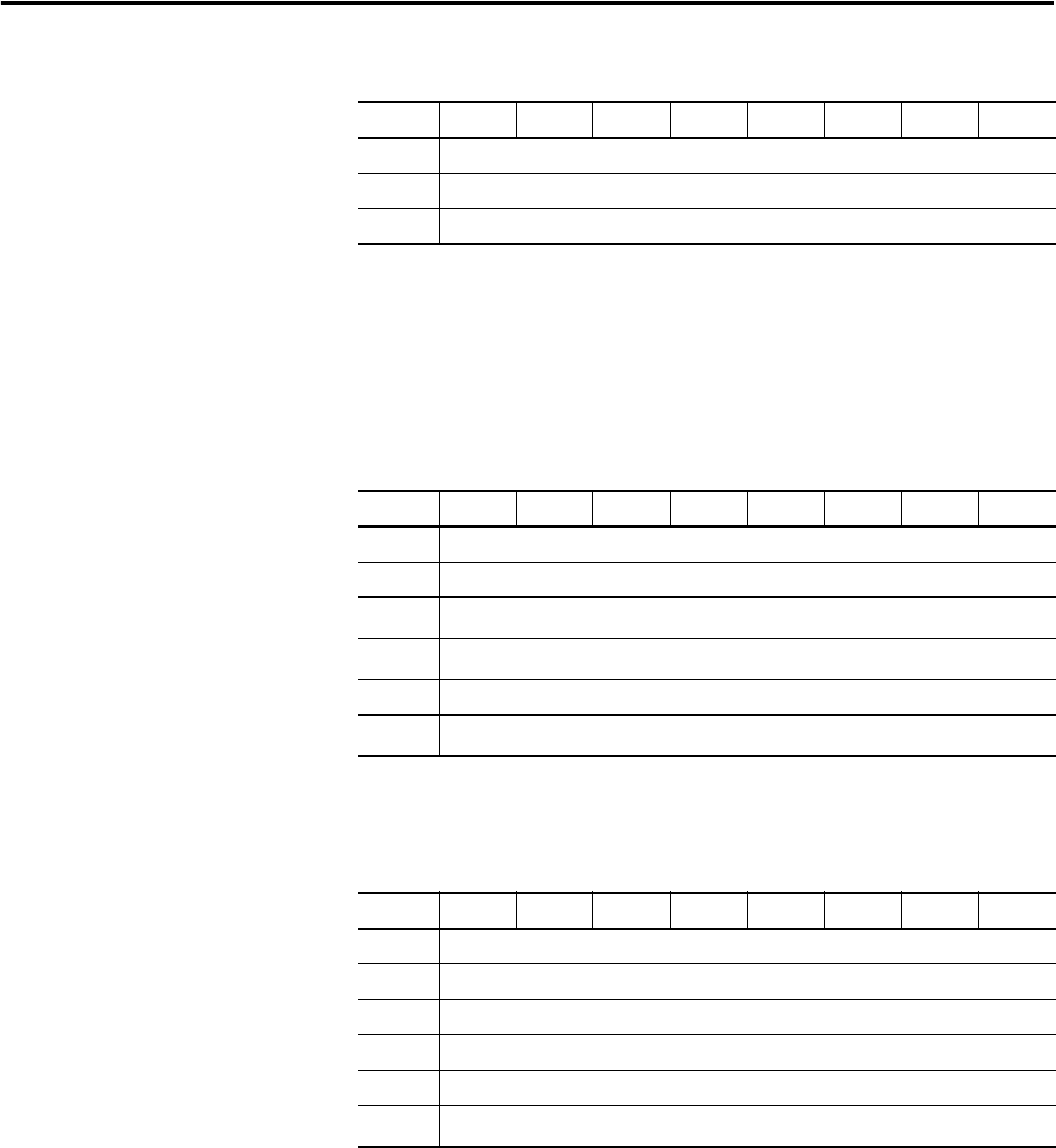
Configuration Assembly Instance 103
Byte Bit 7Bit 6Bit 5Bit 4Bit 3Bit 2Bit 1Bit 0