
Assembly Connections for POINT I/O and ArmorPOINT I/O EtherNet/IP Adapters User Manual
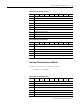
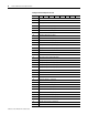
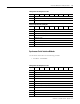
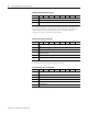
Table Of Contents
- 1734-UM016A-EN-P Assembly Connections for POINT I/O and ArmorPOINT I/O EtherNet/IP Adapters User Manual
- Important User Information
- Table of Contents
- Preface
- Chapter 1 - Introduction
- Chapter 2 - Configuration
- Chapter 3 - Using an Assembly Connection
- Chapter 4 - Assembly Structure
- Chapter 5 - 1734/1738 I/O Module Assembly Information
- Module Assembly Information
- Module Specific Details
- Two-channel Discrete Input Modules
- Four-channel Discrete Input Modules
- Eight-channel Discrete Input Modules
- Two-channel Discrete Output Modules with Status
- Two-channel Discrete Output Modules
- Four-channel Discrete Output Modules with Status
- Four-channel Discrete Output Modules
- Eight-channel Discrete Output Modules with Status
- Eight-channel Discrete Output Modules
- Four-channel Discrete Diagnostic Input Modules
- Two-channel Relay and AC Output Modules
- Four-channel Relay and AC Output Modules
- Sixteen-channel Discrete Diagnostic Input Modules
- Sixteen-channel Discrete Output Modules
- Eight-channel Configurable Discrete Input/Output Modules
- Very High Speed Counter Modules
- Counter Modules
- Two-channel Analog Input Modules
- Four-channel Analog Input Modules
- Eight-channel Analog Input Modules
- Two-channel Analog Output Modules
- Four-channel Analog Output Modules
- Two-channel RTD Input Modules
- Two-channel Thermocouple Input Modules
- Synchronous Serial Interface Modules
- Address Reserve Module
- ASCII Interface Modules
- Index
- Back Cover

Publication 1734-UM016A-EN-P - October 2010
66 1734/1738 I/O Module Assembly Information
7 Alarm Latch Channel 0
8 Notch Filter Channel 0
9 Sensor Type Channel 0
10 Digital Filter Channel 0 (Low Byte)
11 Digital Filter Channel 0 (High Byte)
12 Low Alarm Channel 0 (Low Byte)
13 Low Alarm Channel 0 (High Byte)
14 High Alarm Channel 0 (Low Byte)
15 High Alarm Channel 0 (High Byte)
16 Low Low Alarm Channel 0 (Low Byte)
17 Low Low Alarm Channel 0 (High Byte)
18 High High Alarm Channel 0 (Low Byte)
19 High High Alarm Channel 0 (High Byte)
20 Temperature Units Channel 0
21 Cold Junction Enable Chan 0
22 Cold Junction Offset Chan 0 (Low Byte)
23 Cold Junction Offset Chan 0 (High Byte)
24 Low Engineering Channel 1 (Low Byte)
25 Low Engineering Channel 1 (High Byte)
26 High Engineering Channel 1 (Low Byte)
27 High Engineering Channel 1 (High Byte)
28 Alarm Disable Channel 1
29 Alarm Latch Channel 1
30 Notch Filter Channel 1
31 Sensor Type Channel 1
32 Digital Filter Channel 1 (Low Byte)
33 Digital Filter Channel 1 (High Byte)
34 Low Alarm Channel 1 (Low Byte)
35 Low Alarm Channel 1 (High Byte)
36 High Alarm Channel 1 (Low Byte)
37 High Alarm Channel 1 (High Byte)
38 Low Low Alarm Channel 1 (Low Byte)
39 Low Low Alarm Channel 1 (High Byte)
40 High High Alarm Channel 1 (Low Byte)
41 High High Alarm Channel 1 (High Byte)
42 Temperature Units Channel 1
Configuration Assembly Instance 103
Byte Bit 7Bit 6Bit 5Bit 4Bit 3Bit 2Bit 1Bit 0