
Assembly Connections for POINT I/O and ArmorPOINT I/O EtherNet/IP Adapters User Manual


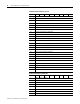
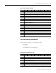
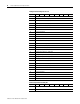
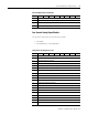
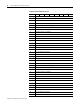
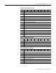
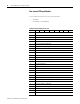
Table Of Contents
- 1734-UM016A-EN-P Assembly Connections for POINT I/O and ArmorPOINT I/O EtherNet/IP Adapters User Manual
- Important User Information
- Table of Contents
- Preface
- Chapter 1 - Introduction
- Chapter 2 - Configuration
- Chapter 3 - Using an Assembly Connection
- Chapter 4 - Assembly Structure
- Chapter 5 - 1734/1738 I/O Module Assembly Information
- Module Assembly Information
- Module Specific Details
- Two-channel Discrete Input Modules
- Four-channel Discrete Input Modules
- Eight-channel Discrete Input Modules
- Two-channel Discrete Output Modules with Status
- Two-channel Discrete Output Modules
- Four-channel Discrete Output Modules with Status
- Four-channel Discrete Output Modules
- Eight-channel Discrete Output Modules with Status
- Eight-channel Discrete Output Modules
- Four-channel Discrete Diagnostic Input Modules
- Two-channel Relay and AC Output Modules
- Four-channel Relay and AC Output Modules
- Sixteen-channel Discrete Diagnostic Input Modules
- Sixteen-channel Discrete Output Modules
- Eight-channel Configurable Discrete Input/Output Modules
- Very High Speed Counter Modules
- Counter Modules
- Two-channel Analog Input Modules
- Four-channel Analog Input Modules
- Eight-channel Analog Input Modules
- Two-channel Analog Output Modules
- Four-channel Analog Output Modules
- Two-channel RTD Input Modules
- Two-channel Thermocouple Input Modules
- Synchronous Serial Interface Modules
- Address Reserve Module
- ASCII Interface Modules
- Index
- Back Cover

Publication 1734-UM016A-EN-P - October 2010
58 1734/1738 I/O Module Assembly Information
120 High High Alarm Channel 6 (Low Byte)
121 High High Alarm Channel 6 (High Byte)
122 Range Channel 6
123 Alarm Latch Channel 6
124 Alarm Disable Channel 6
125 Alignment (reserved = 0)
126 Low Engineering Channel 7 (Low Byte)
127 Low Engineering Channel 7 (High Byte)
128 High Engineering Channel 7 (Low Byte)
129 High Engineering Channel 7 (High Byte)
130 Digital Filter Channel 7 (Low Byte)
131 Digital Filter Channel 7 (High Byte)
132 Low Alarm Channel 7 (Low Byte)
134 Low Alarm Channel 7 (High Byte)
135 High Alarm Channel 7 (High Byte)
136 Low Low Alarm Channel 7 (Low Byte)
137 Low Low Alarm Channel 7 (High Byte)
138 High High Alarm Channel 7 (Low Byte)
139 High High Alarm Channel 7 (High Byte)
140 Range Channel 7
141 Alarm Latch Channel 7
142 Alarm Disable Channel 7
143 Notch Filter
144 Update Rate (Low Byte)
145 Update Rate (High Byte)
Produced Input Data Assembly 101
Byte Bit 7Bit 6Bit 5Bit 4Bit 3Bit 2Bit 1Bit 0
0 Channel 0 Data (Low Byte)
1 Channel 0 Data (High Byte)
2 Channel 1 Data (Low Byte)
3 Channel 1 Data (High Byte)
4 Channel 2 Data (Low Byte)
5 Channel 2 Data (High Byte)
6 Channel 3 Data (Low Byte)
7 Channel 3 Data (High Byte)
Configuration Assembly Instance 123
Byte Bit 7Bit 6Bit 5Bit 4Bit 3Bit 2Bit 1Bit 0