
Assembly Connections for POINT I/O and ArmorPOINT I/O EtherNet/IP Adapters User Manual

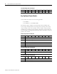

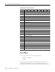
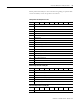
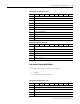
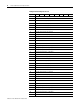
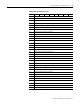
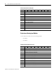
Table Of Contents
- 1734-UM016A-EN-P Assembly Connections for POINT I/O and ArmorPOINT I/O EtherNet/IP Adapters User Manual
- Important User Information
- Table of Contents
- Preface
- Chapter 1 - Introduction
- Chapter 2 - Configuration
- Chapter 3 - Using an Assembly Connection
- Chapter 4 - Assembly Structure
- Chapter 5 - 1734/1738 I/O Module Assembly Information
- Module Assembly Information
- Module Specific Details
- Two-channel Discrete Input Modules
- Four-channel Discrete Input Modules
- Eight-channel Discrete Input Modules
- Two-channel Discrete Output Modules with Status
- Two-channel Discrete Output Modules
- Four-channel Discrete Output Modules with Status
- Four-channel Discrete Output Modules
- Eight-channel Discrete Output Modules with Status
- Eight-channel Discrete Output Modules
- Four-channel Discrete Diagnostic Input Modules
- Two-channel Relay and AC Output Modules
- Four-channel Relay and AC Output Modules
- Sixteen-channel Discrete Diagnostic Input Modules
- Sixteen-channel Discrete Output Modules
- Eight-channel Configurable Discrete Input/Output Modules
- Very High Speed Counter Modules
- Counter Modules
- Two-channel Analog Input Modules
- Four-channel Analog Input Modules
- Eight-channel Analog Input Modules
- Two-channel Analog Output Modules
- Four-channel Analog Output Modules
- Two-channel RTD Input Modules
- Two-channel Thermocouple Input Modules
- Synchronous Serial Interface Modules
- Address Reserve Module
- ASCII Interface Modules
- Index
- Back Cover

Publication 1734-UM016A-EN-P - October 2010
1734/1738 I/O Module Assembly Information 53
41 Digital Filter Channel 2 (High Byte)
42 Low Alarm Channel 2 (Low Byte)
43 Low Alarm Channel 2 (High Byte)
44 High Alarm Channel 2 (Low Byte)
45 High Alarm Channel 2 (High Byte)
46 Low Low Alarm Channel 2 (Low Byte)
47 Low Low Alarm Channel 2 (High Byte)
48 High High Alarm Channel 2 (Low Byte)
49 High High Alarm Channel 2 (High Byte)
50 Range Channel 2
51 Alarm Latch Channel 2
52 Alarm Disable Channel 2
53 Alignment (reserved = 0)
54 Low Engineering Channel 3 (Low Byte)
55 Low Engineering Channel 3 (High Byte)
56 High Engineering Channel 3 (Low Byte)
57 High Engineering Channel 3 (High Byte)
58 Digital Filter Channel 3 (Low Byte)
59 Digital Filter Channel 3 (High Byte)
60 Low Alarm Channel 3 (Low Byte)
61 Low Alarm Channel 3 (High Byte)
62 High Alarm Channel 3 (Low Byte)
63 High Alarm Channel 3 (High Byte)
64 Low Low Alarm Channel 3 (Low Byte)
65 Low Low Alarm Channel 3 (High Byte)
66 High High Alarm Channel 3 (Low Byte)
67 High High Alarm Channel 3 (High Byte)
68 Range Channel 3
69 Alarm Latch Channel 3
70 Alarm Disable Channel 3
71 Notch Filter
72 Update Rate (Low Byte)
73 Update Rate (High Byte)
Configuration Assembly Instance 123
Byte Bit 7Bit 6Bit 5Bit 4Bit 3Bit 2Bit 1Bit 0