
Assembly Connections for POINT I/O and ArmorPOINT I/O EtherNet/IP Adapters User Manual

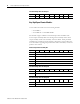

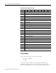
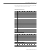
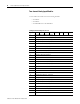
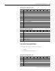
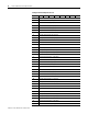
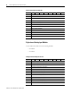
Table Of Contents
- 1734-UM016A-EN-P Assembly Connections for POINT I/O and ArmorPOINT I/O EtherNet/IP Adapters User Manual
- Important User Information
- Table of Contents
- Preface
- Chapter 1 - Introduction
- Chapter 2 - Configuration
- Chapter 3 - Using an Assembly Connection
- Chapter 4 - Assembly Structure
- Chapter 5 - 1734/1738 I/O Module Assembly Information
- Module Assembly Information
- Module Specific Details
- Two-channel Discrete Input Modules
- Four-channel Discrete Input Modules
- Eight-channel Discrete Input Modules
- Two-channel Discrete Output Modules with Status
- Two-channel Discrete Output Modules
- Four-channel Discrete Output Modules with Status
- Four-channel Discrete Output Modules
- Eight-channel Discrete Output Modules with Status
- Eight-channel Discrete Output Modules
- Four-channel Discrete Diagnostic Input Modules
- Two-channel Relay and AC Output Modules
- Four-channel Relay and AC Output Modules
- Sixteen-channel Discrete Diagnostic Input Modules
- Sixteen-channel Discrete Output Modules
- Eight-channel Configurable Discrete Input/Output Modules
- Very High Speed Counter Modules
- Counter Modules
- Two-channel Analog Input Modules
- Four-channel Analog Input Modules
- Eight-channel Analog Input Modules
- Two-channel Analog Output Modules
- Four-channel Analog Output Modules
- Two-channel RTD Input Modules
- Two-channel Thermocouple Input Modules
- Synchronous Serial Interface Modules
- Address Reserve Module
- ASCII Interface Modules
- Index
- Back Cover

Publication 1734-UM016A-EN-P - October 2010
1734/1738 I/O Module Assembly Information 49
default produced assembly. For more information regarding the specific fields
of these assemblies, consult the product's user manual.
Configuration Assembly Instance 123
Byte Bit 7Bit 6Bit 5Bit 4Bit 3Bit 2Bit 1Bit 0
0 Counter Configuration
1 Filter Selection
2 Decimal Position
3 Reserved
4 Time Base (low byte)
5 Time Base (high byte)
6 Gate Interval
7Scalar
8 Rollover Value [Low Byte]
9 Rollover Value [1]
10 Rollover Value [2]
11 Rollover Value [High Byte]
12 Preset Value [Low Byte]
13 Preset Value [1]
14 Preset Value [2]
15 Preset Value [High Byte]
16 Counter Control SSV
17 Reserved (set to 0)
Produced Input Data Assembly 102
Byte Bit 7Bit 6Bit 5Bit 4Bit 3Bit 2Bit 1Bit 0
0 Stored Channel Data [Low Byte]
1 Stored Channel Data [1]
2 Stored Channel Data [2]
3 Stored Channel Data [High Byte]
4 Status (Low Byte)
5 Status (High Byte)
Consumed Output Data Assembly 105
Byte Bit 7Bit 6Bit 5Bit 4Bit 3Bit 2Bit 1Bit 0
0 Counter Control