
Assembly Connections for POINT I/O and ArmorPOINT I/O EtherNet/IP Adapters User Manual

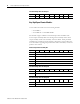

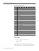
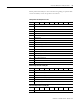
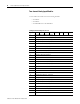
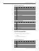
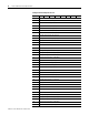
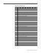
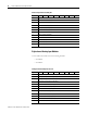
Table Of Contents
- 1734-UM016A-EN-P Assembly Connections for POINT I/O and ArmorPOINT I/O EtherNet/IP Adapters User Manual
- Important User Information
- Table of Contents
- Preface
- Chapter 1 - Introduction
- Chapter 2 - Configuration
- Chapter 3 - Using an Assembly Connection
- Chapter 4 - Assembly Structure
- Chapter 5 - 1734/1738 I/O Module Assembly Information
- Module Assembly Information
- Module Specific Details
- Two-channel Discrete Input Modules
- Four-channel Discrete Input Modules
- Eight-channel Discrete Input Modules
- Two-channel Discrete Output Modules with Status
- Two-channel Discrete Output Modules
- Four-channel Discrete Output Modules with Status
- Four-channel Discrete Output Modules
- Eight-channel Discrete Output Modules with Status
- Eight-channel Discrete Output Modules
- Four-channel Discrete Diagnostic Input Modules
- Two-channel Relay and AC Output Modules
- Four-channel Relay and AC Output Modules
- Sixteen-channel Discrete Diagnostic Input Modules
- Sixteen-channel Discrete Output Modules
- Eight-channel Configurable Discrete Input/Output Modules
- Very High Speed Counter Modules
- Counter Modules
- Two-channel Analog Input Modules
- Four-channel Analog Input Modules
- Eight-channel Analog Input Modules
- Two-channel Analog Output Modules
- Four-channel Analog Output Modules
- Two-channel RTD Input Modules
- Two-channel Thermocouple Input Modules
- Synchronous Serial Interface Modules
- Address Reserve Module
- ASCII Interface Modules
- Index
- Back Cover
Publication 1734-UM016A-EN-P - October 2010
46 1734/1738 I/O Module Assembly Information
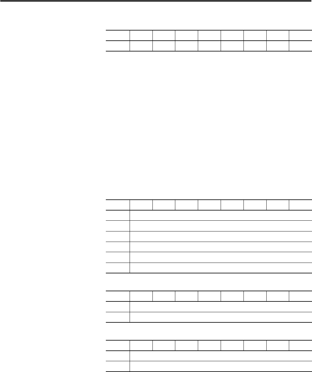
Very High Speed Counter Modules
Use the tables shown below for the following modules:
• 1734-VHSC5
• 1734-VHSC25 or 1738-VHSC24M23
The modules support 3 different consumed output data assemblies. The
Active Output Assembly field of the Configuration assembly selects which
output assembly will be used. Assembly 105 is the default. Other produced
assemblies are possible but require separate configuration of the module. For
more information regarding the specific fields of these assemblies, consult the
product's user manual.
Consumed Output Data Assembly 34
Byte Bit 7Bit 6Bit 5Bit 4Bit 3Bit 2Bit 1Bit 0
0 Ch 7 Ch 6 Ch 5 Ch 4 Ch 3 Ch 2 Ch 1 Ch 0
Produced Input Data Assembly 102
Byte Bit 7Bit 6Bit 5Bit 4Bit 3Bit 2Bit 1Bit 0
0 Stored Channel Data [Low Byte]
1 Stored Channel Data [1]
2 Stored Channel Data [2]
3 Stored Channel Data [High Byte]
4 Status (Low Byte)
5 Status (High Byte)
Consumed Output Data Assembly 105
Byte Bit 7Bit 6Bit 5Bit 4Bit 3Bit 2Bit 1Bit 0
0 Counter Control
1 Output Control
Consumed Output Data Assembly 106
Byte Bit 7Bit 6Bit 5Bit 4Bit 3Bit 2Bit 1Bit 0
0 PWM Value (Low Byte)
1 PWM Value (High Byte)