
Assembly Connections for POINT I/O and ArmorPOINT I/O EtherNet/IP Adapters User Manual
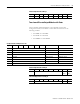
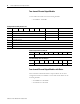
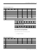
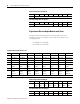
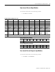
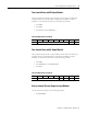
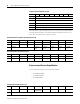
Table Of Contents
- 1734-UM016A-EN-P Assembly Connections for POINT I/O and ArmorPOINT I/O EtherNet/IP Adapters User Manual
- Important User Information
- Table of Contents
- Preface
- Chapter 1 - Introduction
- Chapter 2 - Configuration
- Chapter 3 - Using an Assembly Connection
- Chapter 4 - Assembly Structure
- Chapter 5 - 1734/1738 I/O Module Assembly Information
- Module Assembly Information
- Module Specific Details
- Two-channel Discrete Input Modules
- Four-channel Discrete Input Modules
- Eight-channel Discrete Input Modules
- Two-channel Discrete Output Modules with Status
- Two-channel Discrete Output Modules
- Four-channel Discrete Output Modules with Status
- Four-channel Discrete Output Modules
- Eight-channel Discrete Output Modules with Status
- Eight-channel Discrete Output Modules
- Four-channel Discrete Diagnostic Input Modules
- Two-channel Relay and AC Output Modules
- Four-channel Relay and AC Output Modules
- Sixteen-channel Discrete Diagnostic Input Modules
- Sixteen-channel Discrete Output Modules
- Eight-channel Configurable Discrete Input/Output Modules
- Very High Speed Counter Modules
- Counter Modules
- Two-channel Analog Input Modules
- Four-channel Analog Input Modules
- Eight-channel Analog Input Modules
- Two-channel Analog Output Modules
- Four-channel Analog Output Modules
- Two-channel RTD Input Modules
- Two-channel Thermocouple Input Modules
- Synchronous Serial Interface Modules
- Address Reserve Module
- ASCII Interface Modules
- Index
- Back Cover
Publication 1734-UM016A-EN-P - October 2010
1734/1738 I/O Module Assembly Information 39
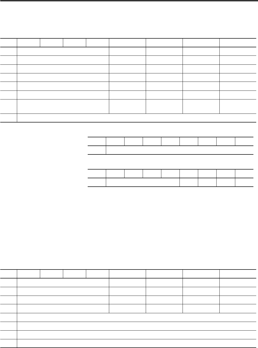
Four-channel Discrete Output Modules
Use the tables shown below for the following modules:
• 1734-OB4 or 1738-OB4
Configuration Assembly Instance 123
Byte Bit 7 Bit 6 Bit 5 Bit 4 Bit 3 Bit 2 Bit 1 Bit 0
0 Reserved Fault State 3 Fault State 2 Fault State 1 Fault State 0
1 Reserved Fault Value 3 Fault Value 2 Fault Value 1 Fault Value 0
2 Reserved Idle State 3 Idle State 2 Idle State 1 Idle State 0
3 Reserved Idle Value 3 Idle Value 2 Idle Value 1 Idle Value 0
4 Reserved Enable No Load 3 Enable No Load 2 Enable No Load 1 Enable No Load 0
5 Reserved Reset mode 3 Reset mode 2 Reset mode 1 Reset mode 0
6 Reserved Enable Latched
Alarms 3
Enable Latched
Alarms 2
Enable Latched
Alarms 1
Enable Latched
Alarms 0
7 Pad
Produced Input Data Assembly 43
ByteBit 7Bit 6Bit 5Bit 4Bit 3Bit 2Bit 1Bit 0
0 Reserved
Consumed Output Data Assembly 33
ByteBit 7Bit 6Bit 5Bit 4Bit 3Bit 2Bit 1Bit 0
0 Reserved Ch 3 Ch 2 Ch 1 Ch 0
Configuration Assembly Instance 123
Byte Bit 7 Bit 6 Bit 5 Bit 4 Bit 3 Bit 2 Bit 1 Bit 0
0 Reserved Fault State 3 Fault State 2 Fault State 1 Fault State 0
1 Reserved Fault Value 3 Fault Value 2 Fault Value 1 Fault Value 0
2 Reserved Idle State 3 Idle State 2 Idle State 1 Idle State 0
3 Reserved Idle Value 3 Idle Value 2 Idle Value 1 Idle Value 0
4 Reserved (Set to 0)
5 Reserved (Set to 0)
6 Reserved (Set to 0)
7 Pad