
Assembly Connections for POINT I/O and ArmorPOINT I/O EtherNet/IP Adapters User Manual
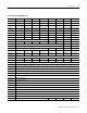
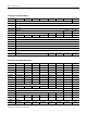
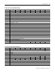
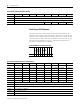

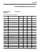
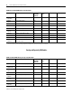
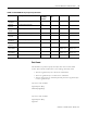
Table Of Contents
- 1734-UM016A-EN-P Assembly Connections for POINT I/O and ArmorPOINT I/O EtherNet/IP Adapters User Manual
- Important User Information
- Table of Contents
- Preface
- Chapter 1 - Introduction
- Chapter 2 - Configuration
- Chapter 3 - Using an Assembly Connection
- Chapter 4 - Assembly Structure
- Chapter 5 - 1734/1738 I/O Module Assembly Information
- Module Assembly Information
- Module Specific Details
- Two-channel Discrete Input Modules
- Four-channel Discrete Input Modules
- Eight-channel Discrete Input Modules
- Two-channel Discrete Output Modules with Status
- Two-channel Discrete Output Modules
- Four-channel Discrete Output Modules with Status
- Four-channel Discrete Output Modules
- Eight-channel Discrete Output Modules with Status
- Eight-channel Discrete Output Modules
- Four-channel Discrete Diagnostic Input Modules
- Two-channel Relay and AC Output Modules
- Four-channel Relay and AC Output Modules
- Sixteen-channel Discrete Diagnostic Input Modules
- Sixteen-channel Discrete Output Modules
- Eight-channel Configurable Discrete Input/Output Modules
- Very High Speed Counter Modules
- Counter Modules
- Two-channel Analog Input Modules
- Four-channel Analog Input Modules
- Eight-channel Analog Input Modules
- Two-channel Analog Output Modules
- Four-channel Analog Output Modules
- Two-channel RTD Input Modules
- Two-channel Thermocouple Input Modules
- Synchronous Serial Interface Modules
- Address Reserve Module
- ASCII Interface Modules
- Index
- Back Cover
Publication 1734-UM016A-EN-P - October 2010
28 Assembly Structure
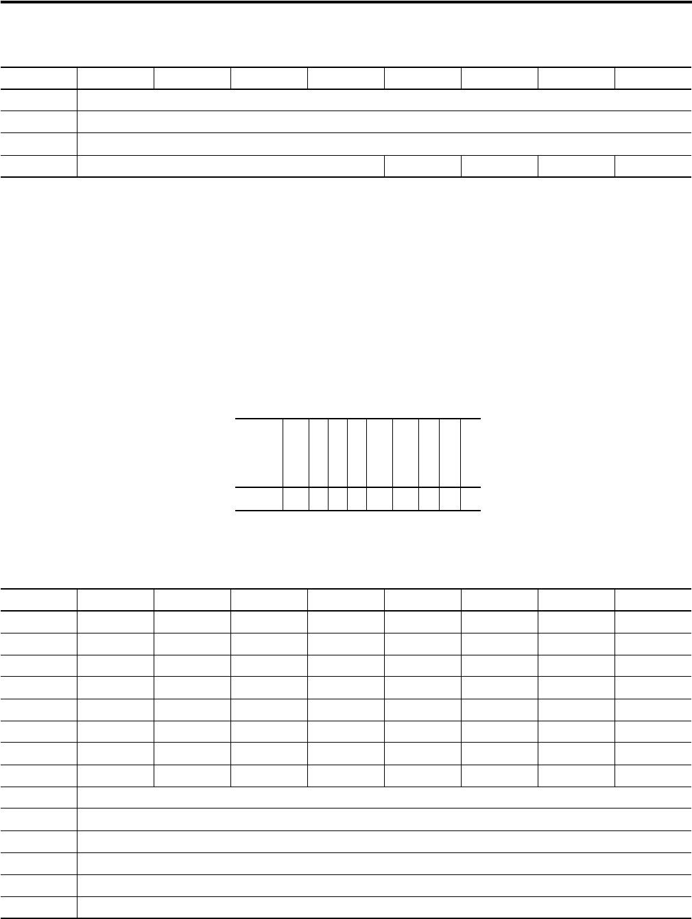
Fixed Size per Slot Alignment
The following chassis is used to demonstrate how the Fixed Size per Slot
alignment option might be used. This chassis is built to show a machine that
sometimes uses 5 analog modules, but usually only needs 3 modules. In order
to maintain data structure consistency (and therefore the same control logic),
Fixed Size per Slot alignment of 6 bytes is used and the unused slots are
populated with Address Reserve Modules.
Consume 11 Slot 10 ASCII Data 4
Consume 12 Slot 10 ASCII Data 5
Consume 13 Slot 10 ASCII Data End of String Delimiter
Consume 14 Reserved Slot 12 Bit 3 Slot 12 Bit 2 Slot 12 Bit 1 Slot 12 Bit 0
Consumed Assembly, Double Word Aligned
Byte Bit 7 Bit 6 Bit5 Bit 4 Bit 3 Bit 2 Bit 1 Bit 0
Example POINT system with unused slots
Cat # A
E
N
T
I
E
2
C
I
E
2
C
I
E
2
C
A
R
M
A
R
M
I
B
4
I
B
4
I
B
4
Slot # 012345678
Produced Assembly, Fixed Size per Slot Alignment
Byte Bit 7 Bit 6 Bit5 Bit 4 Bit 3 Bit 2 Bit 1 Bit 0
Produce 0 Slot 7 status Slot 6 status Slot 5 status Slot 4 status Slot 3 status Slot 2 status Slot1 status Slot 0 status
Produce 1 Slot 15 status Slot 14 status Slot 13 status Slot 12 status Slot 11 status Slot 10 status Slot 9 status Slot 8 status
Produce 2 Slot 23 status Slot 22 status Slot 21 status Slot 20 status Slot 19 status Slot 18 status Slot 17 status Slot 16 status
Produce 3 Slot 31 status Slot 30 status Slot 29 status Slot 28 status Slot 27 status Slot 26 status Slot 25 status Slot 24 status
Produce 4 Slot 39 status Slot 38 status Slot 37 status Slot 36 status Slot 35 status Slot 34 status Slot 33 status Slot 32 status
Produce 5 Slot 47 status Slot 46 status Slot 45 status Slot 44 status Slot 43 status Slot 42 status Slot 41 status Slot 40 status
Produce 6 Slot 55 status Slot 54 status Slot 53 status Slot 52 status Slot 51 status Slot 50 status Slot 49 status Slot 48 status
Produce 7 Slot 63 status Slot 62 status Slot 61 status Slot 60 status Slot 59 status Slot 58 status Slot 57 status Slot 56 status
Produce 8 Slot 1 Channel 0 - Low Byte
Produce 9 Slot 1 Channel 0 - High Byte
Produce 10 Slot 1 Channel 1 - Low Byte
Produce 11 Slot 1 Channel 1 - High Byte
Produce 12 Slot 1 Channel 0 - Status
Produce 13 Slot 1 Channel 1 - Status