
Assembly Connections for POINT I/O and ArmorPOINT I/O EtherNet/IP Adapters User Manual
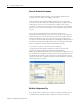
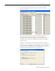
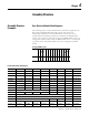
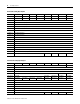
Table Of Contents
- 1734-UM016A-EN-P Assembly Connections for POINT I/O and ArmorPOINT I/O EtherNet/IP Adapters User Manual
- Important User Information
- Table of Contents
- Preface
- Chapter 1 - Introduction
- Chapter 2 - Configuration
- Chapter 3 - Using an Assembly Connection
- Chapter 4 - Assembly Structure
- Chapter 5 - 1734/1738 I/O Module Assembly Information
- Module Assembly Information
- Module Specific Details
- Two-channel Discrete Input Modules
- Four-channel Discrete Input Modules
- Eight-channel Discrete Input Modules
- Two-channel Discrete Output Modules with Status
- Two-channel Discrete Output Modules
- Four-channel Discrete Output Modules with Status
- Four-channel Discrete Output Modules
- Eight-channel Discrete Output Modules with Status
- Eight-channel Discrete Output Modules
- Four-channel Discrete Diagnostic Input Modules
- Two-channel Relay and AC Output Modules
- Four-channel Relay and AC Output Modules
- Sixteen-channel Discrete Diagnostic Input Modules
- Sixteen-channel Discrete Output Modules
- Eight-channel Configurable Discrete Input/Output Modules
- Very High Speed Counter Modules
- Counter Modules
- Two-channel Analog Input Modules
- Four-channel Analog Input Modules
- Eight-channel Analog Input Modules
- Two-channel Analog Output Modules
- Four-channel Analog Output Modules
- Two-channel RTD Input Modules
- Two-channel Thermocouple Input Modules
- Synchronous Serial Interface Modules
- Address Reserve Module
- ASCII Interface Modules
- Index
- Back Cover
Publication 1734-UM016A-EN-P - October 2010
Using an Assembly Connection 21
For more information on configuration, see 1734/1738 I/O Module
Assembly Information.
After the configuration has been entered into the tag, remember to
save the RSLogix 5000 project. The tags are only retained upon a save. Also
remember that any configuration added here must be reflected in the
Configuration Size of the Connection Parameters entered on the Module
Properties dialog.
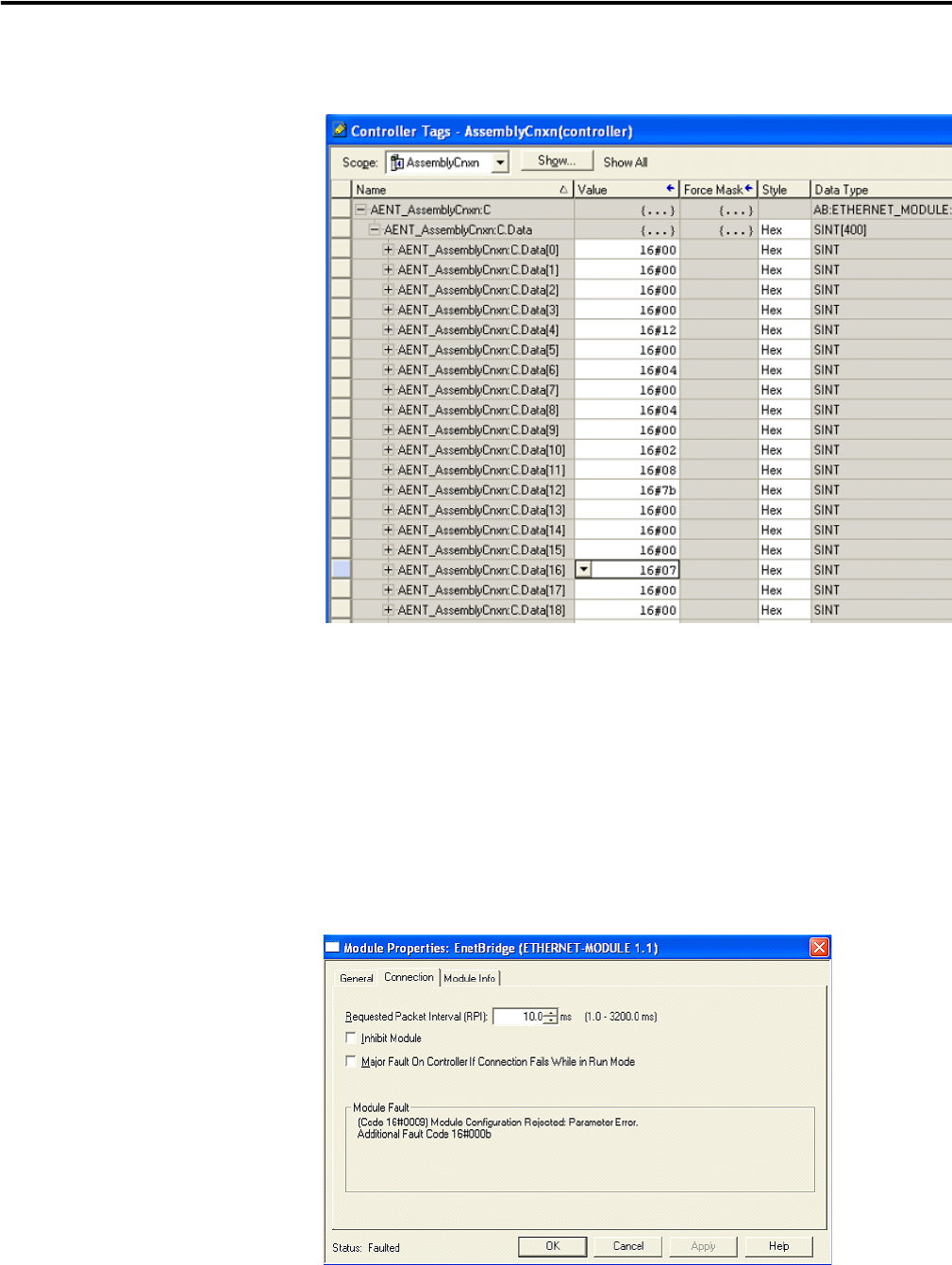
If any part of the configuration assembly is wrong (either the minimal
assembly or a portion directed to an I/O module), the connection request will
be rejected with the General Return Code indicating an Error in the Data
Segment (0x09). The Extended Error code will indicate the byte offset into the
configuration data segment where the error was detected.