
Assembly Connections for POINT I/O and ArmorPOINT I/O EtherNet/IP Adapters User Manual
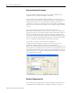
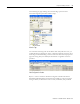
Table Of Contents
- 1734-UM016A-EN-P Assembly Connections for POINT I/O and ArmorPOINT I/O EtherNet/IP Adapters User Manual
- Important User Information
- Table of Contents
- Preface
- Chapter 1 - Introduction
- Chapter 2 - Configuration
- Chapter 3 - Using an Assembly Connection
- Chapter 4 - Assembly Structure
- Chapter 5 - 1734/1738 I/O Module Assembly Information
- Module Assembly Information
- Module Specific Details
- Two-channel Discrete Input Modules
- Four-channel Discrete Input Modules
- Eight-channel Discrete Input Modules
- Two-channel Discrete Output Modules with Status
- Two-channel Discrete Output Modules
- Four-channel Discrete Output Modules with Status
- Four-channel Discrete Output Modules
- Eight-channel Discrete Output Modules with Status
- Eight-channel Discrete Output Modules
- Four-channel Discrete Diagnostic Input Modules
- Two-channel Relay and AC Output Modules
- Four-channel Relay and AC Output Modules
- Sixteen-channel Discrete Diagnostic Input Modules
- Sixteen-channel Discrete Output Modules
- Eight-channel Configurable Discrete Input/Output Modules
- Very High Speed Counter Modules
- Counter Modules
- Two-channel Analog Input Modules
- Four-channel Analog Input Modules
- Eight-channel Analog Input Modules
- Two-channel Analog Output Modules
- Four-channel Analog Output Modules
- Two-channel RTD Input Modules
- Two-channel Thermocouple Input Modules
- Synchronous Serial Interface Modules
- Address Reserve Module
- ASCII Interface Modules
- Index
- Back Cover
Publication 1734-UM016A-EN-P - October 2010
20 Using an Assembly Connection
and consumed alignment choice is Double Word alignment which is
enumerated as a 4. See the following table for valid alignment values.
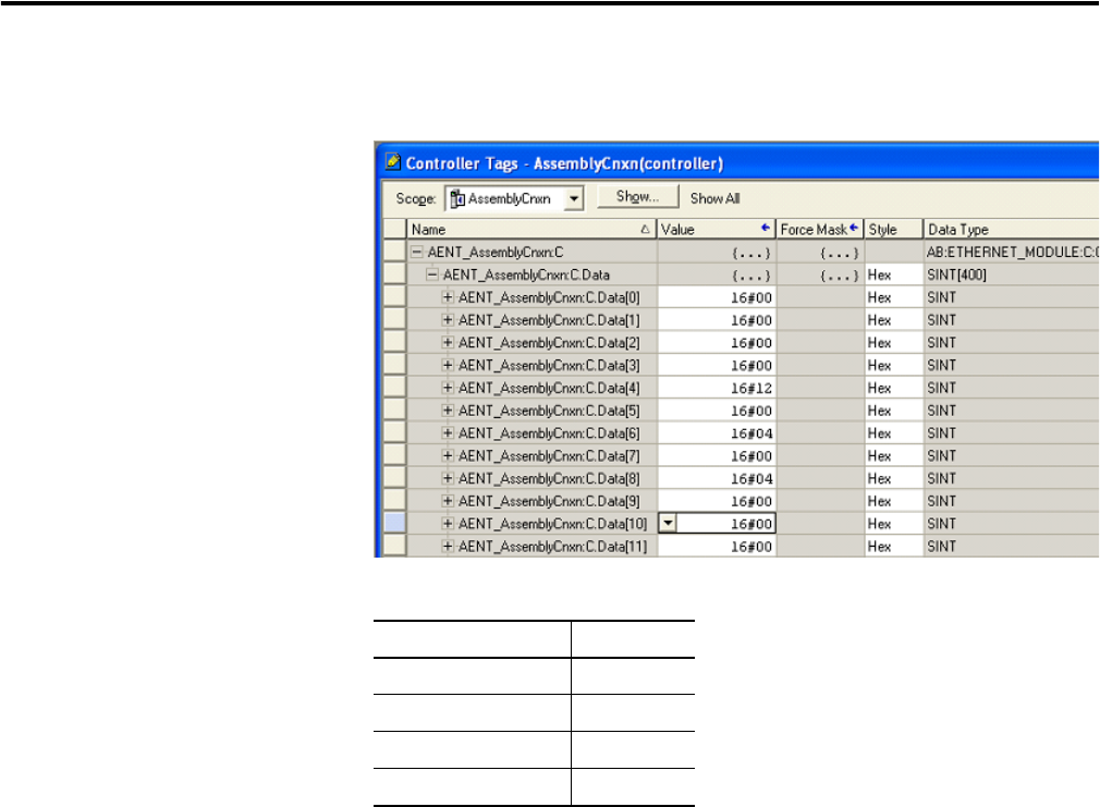
Add I/O Module Configuration
If individual module configuration is required, it can be appended to
the configuration header. In the example shown below a 1734-OB4E module
is being configured. Byte 10 indicates that the data is to be sent to slot 2. Byte
11 specifies the size of the data as 8 bytes. Bytes 12 and 13 specify the OB4E
module configuration assembly instance 0x7B. The instance number is entered
in little endian (least significant byte first). In byte 16 the value of 7 indicates
that when the module is in Idle mode, Hold Last State should be enabled for
channels 0, 1, and 2 but not channel 3. If more module configuration is
needed, it could begin at byte 22 with the slot number of the next module to
be configured.
Alignment choices for configuration header
Alignment Choice Value
Byte 0
Word 2
Double Word 4
Fixed size per slot 0xFF