
Assembly Connections for POINT I/O and ArmorPOINT I/O EtherNet/IP Adapters User Manual
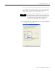
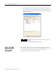
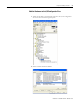
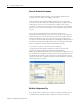
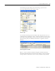
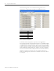
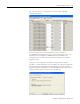
Table Of Contents
- 1734-UM016A-EN-P Assembly Connections for POINT I/O and ArmorPOINT I/O EtherNet/IP Adapters User Manual
- Important User Information
- Table of Contents
- Preface
- Chapter 1 - Introduction
- Chapter 2 - Configuration
- Chapter 3 - Using an Assembly Connection
- Chapter 4 - Assembly Structure
- Chapter 5 - 1734/1738 I/O Module Assembly Information
- Module Assembly Information
- Module Specific Details
- Two-channel Discrete Input Modules
- Four-channel Discrete Input Modules
- Eight-channel Discrete Input Modules
- Two-channel Discrete Output Modules with Status
- Two-channel Discrete Output Modules
- Four-channel Discrete Output Modules with Status
- Four-channel Discrete Output Modules
- Eight-channel Discrete Output Modules with Status
- Eight-channel Discrete Output Modules
- Four-channel Discrete Diagnostic Input Modules
- Two-channel Relay and AC Output Modules
- Four-channel Relay and AC Output Modules
- Sixteen-channel Discrete Diagnostic Input Modules
- Sixteen-channel Discrete Output Modules
- Eight-channel Configurable Discrete Input/Output Modules
- Very High Speed Counter Modules
- Counter Modules
- Two-channel Analog Input Modules
- Four-channel Analog Input Modules
- Eight-channel Analog Input Modules
- Two-channel Analog Output Modules
- Four-channel Analog Output Modules
- Two-channel RTD Input Modules
- Two-channel Thermocouple Input Modules
- Synchronous Serial Interface Modules
- Address Reserve Module
- ASCII Interface Modules
- Index
- Back Cover
Publication 1734-UM016A-EN-P - October 2010
Using an Assembly Connection 19
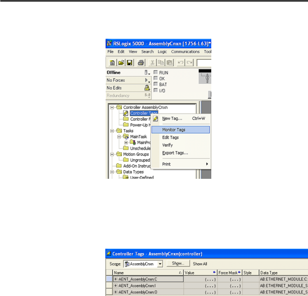
Controller Tags by right-clicking the Controller Tags option from the
Controller Organizer pane. Select Monitor Tags.
Monitor Tags
You should see three Tags with the module's name. They will have an C, I, or
O suffix denoting Configuration, Input, or Output respectively. Note that the I
and O Tags are sized according to the sizes that were entered on the properties
page. The C Tag always has 400 bytes allocated for it regardless of the size
specified.
Add Configuration Header
Bytes 0…9 must contain the minimum configuration header information
described in Minimal Adapter Configuration Assembly. As can be seen from
the figure below, the Chassis Size is set to 0x12 (18 decimal). The produced