
Assembly Connections for POINT I/O and ArmorPOINT I/O EtherNet/IP Adapters User Manual
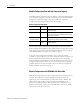
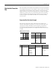
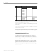
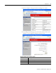
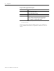

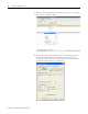
Table Of Contents
- 1734-UM016A-EN-P Assembly Connections for POINT I/O and ArmorPOINT I/O EtherNet/IP Adapters User Manual
- Important User Information
- Table of Contents
- Preface
- Chapter 1 - Introduction
- Chapter 2 - Configuration
- Chapter 3 - Using an Assembly Connection
- Chapter 4 - Assembly Structure
- Chapter 5 - 1734/1738 I/O Module Assembly Information
- Module Assembly Information
- Module Specific Details
- Two-channel Discrete Input Modules
- Four-channel Discrete Input Modules
- Eight-channel Discrete Input Modules
- Two-channel Discrete Output Modules with Status
- Two-channel Discrete Output Modules
- Four-channel Discrete Output Modules with Status
- Four-channel Discrete Output Modules
- Eight-channel Discrete Output Modules with Status
- Eight-channel Discrete Output Modules
- Four-channel Discrete Diagnostic Input Modules
- Two-channel Relay and AC Output Modules
- Four-channel Relay and AC Output Modules
- Sixteen-channel Discrete Diagnostic Input Modules
- Sixteen-channel Discrete Output Modules
- Eight-channel Configurable Discrete Input/Output Modules
- Very High Speed Counter Modules
- Counter Modules
- Two-channel Analog Input Modules
- Four-channel Analog Input Modules
- Eight-channel Analog Input Modules
- Two-channel Analog Output Modules
- Four-channel Analog Output Modules
- Two-channel RTD Input Modules
- Two-channel Thermocouple Input Modules
- Synchronous Serial Interface Modules
- Address Reserve Module
- ASCII Interface Modules
- Index
- Back Cover
Publication 1734-UM016A-EN-P - October 2010
Configuration 11
1. Open the adapter's web page and select the Diagnostics folder.
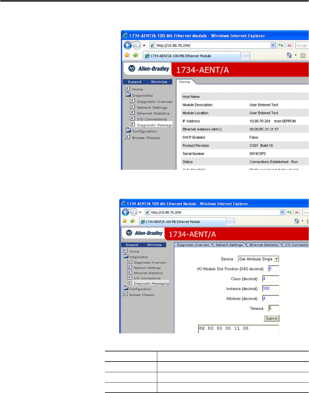
2. On the Diagnostic Messaging tab, enter the Slot, Class, Instance, and
Attribute to get the adapter's calculated connection sizes.
Diagnostic Messaging Field Description
Field Description
Service Get Attribute Single
Slot Position 0
Class 4