
Assembly Connections for POINT I/O and ArmorPOINT I/O EtherNet/IP Adapters User Manual
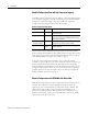
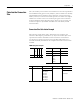
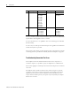

Table Of Contents
- 1734-UM016A-EN-P Assembly Connections for POINT I/O and ArmorPOINT I/O EtherNet/IP Adapters User Manual
- Important User Information
- Table of Contents
- Preface
- Chapter 1 - Introduction
- Chapter 2 - Configuration
- Chapter 3 - Using an Assembly Connection
- Chapter 4 - Assembly Structure
- Chapter 5 - 1734/1738 I/O Module Assembly Information
- Module Assembly Information
- Module Specific Details
- Two-channel Discrete Input Modules
- Four-channel Discrete Input Modules
- Eight-channel Discrete Input Modules
- Two-channel Discrete Output Modules with Status
- Two-channel Discrete Output Modules
- Four-channel Discrete Output Modules with Status
- Four-channel Discrete Output Modules
- Eight-channel Discrete Output Modules with Status
- Eight-channel Discrete Output Modules
- Four-channel Discrete Diagnostic Input Modules
- Two-channel Relay and AC Output Modules
- Four-channel Relay and AC Output Modules
- Sixteen-channel Discrete Diagnostic Input Modules
- Sixteen-channel Discrete Output Modules
- Eight-channel Configurable Discrete Input/Output Modules
- Very High Speed Counter Modules
- Counter Modules
- Two-channel Analog Input Modules
- Four-channel Analog Input Modules
- Eight-channel Analog Input Modules
- Two-channel Analog Output Modules
- Four-channel Analog Output Modules
- Two-channel RTD Input Modules
- Two-channel Thermocouple Input Modules
- Synchronous Serial Interface Modules
- Address Reserve Module
- ASCII Interface Modules
- Index
- Back Cover
Publication 1734-UM016A-EN-P - October 2010
10 Configuration
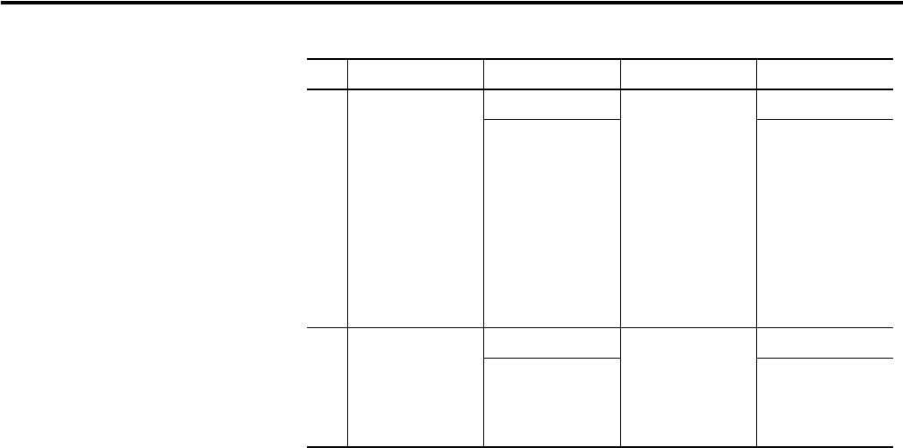
In row 1, the data is packed on byte boundaries. This is the most efficient data
representation when alignment is not a concern.
In row 2 the data for slot 1 is padded so that slot 2's data began on a Double
Word boundary.
In row 3 every slot takes up the selected size per slot regardless of whether that
module has any data to produce.
This section touches briefly on data alignment. More comprehensive examples
of data alignment are provided in Assembly Structure Examples on page 23.
Troubleshooting Connection Size Errors
If the adapter returns the Invalid Connection Size error in response to a
connection request, it is possible to query the adapter for its calculated size.
This section highlights a technique that can be used to help resolve connection
size errors.
The adapter cannot validate connection sizes until the request to open the
connection is received. It is within that request that the adapter receives the
alignment choice and status election. Based on all the information in the
request and the modules present, the request may be rejected by the adapter
because of a size error.
2 Double Word 19 bytes Double Word 5 bytes
status 8 bytes
slot 1 byte
slot 1 pad
slot 1 pad
slot 1 pad
slot 2 int
slot 2 int
slot 2 byte
slot 2 byte
slot 3 byte
run / idle 4 bytes
slot 3 byte
3 6 bytes per slot 26 bytes 1 byte per slot 7 bytes
status 8 bytes
slot 1 6 bytes
slot 2 6 bytes
slot 3 6 bytes
run /idle 4 bytes
slot 1 byte
slot 2 byte
slot 3 byte
T → O alignment T → O size O → T alignment O → T size