
Assembly Connections for POINT I/O and ArmorPOINT I/O EtherNet/IP Adapters User Manual

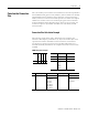
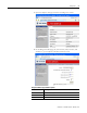
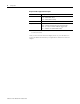

Table Of Contents
- 1734-UM016A-EN-P Assembly Connections for POINT I/O and ArmorPOINT I/O EtherNet/IP Adapters User Manual
- Important User Information
- Table of Contents
- Preface
- Chapter 1 - Introduction
- Chapter 2 - Configuration
- Chapter 3 - Using an Assembly Connection
- Chapter 4 - Assembly Structure
- Chapter 5 - 1734/1738 I/O Module Assembly Information
- Module Assembly Information
- Module Specific Details
- Two-channel Discrete Input Modules
- Four-channel Discrete Input Modules
- Eight-channel Discrete Input Modules
- Two-channel Discrete Output Modules with Status
- Two-channel Discrete Output Modules
- Four-channel Discrete Output Modules with Status
- Four-channel Discrete Output Modules
- Eight-channel Discrete Output Modules with Status
- Eight-channel Discrete Output Modules
- Four-channel Discrete Diagnostic Input Modules
- Two-channel Relay and AC Output Modules
- Four-channel Relay and AC Output Modules
- Sixteen-channel Discrete Diagnostic Input Modules
- Sixteen-channel Discrete Output Modules
- Eight-channel Configurable Discrete Input/Output Modules
- Very High Speed Counter Modules
- Counter Modules
- Two-channel Analog Input Modules
- Four-channel Analog Input Modules
- Eight-channel Analog Input Modules
- Two-channel Analog Output Modules
- Four-channel Analog Output Modules
- Two-channel RTD Input Modules
- Two-channel Thermocouple Input Modules
- Synchronous Serial Interface Modules
- Address Reserve Module
- ASCII Interface Modules
- Index
- Back Cover
Publication 1734-UM016A-EN-P - October 2010
Configuration 9
Calculate the Connection
Size
The I/O assembly size is limited to the maximum size that can be specified in
the standard Forward_Open service (509 bytes). The size needs to be manually
calculated based on the alignment choices, inclusion of the optional status
header, and the I/O sizes for the modules present in the chassis. The adapter
validates the connection size in the forward open against what it calculates
from the backplane and the alignment choice. If the two do not match, the
connection request is rejected with extended error code 0x0109, Invalid
Connection Size.
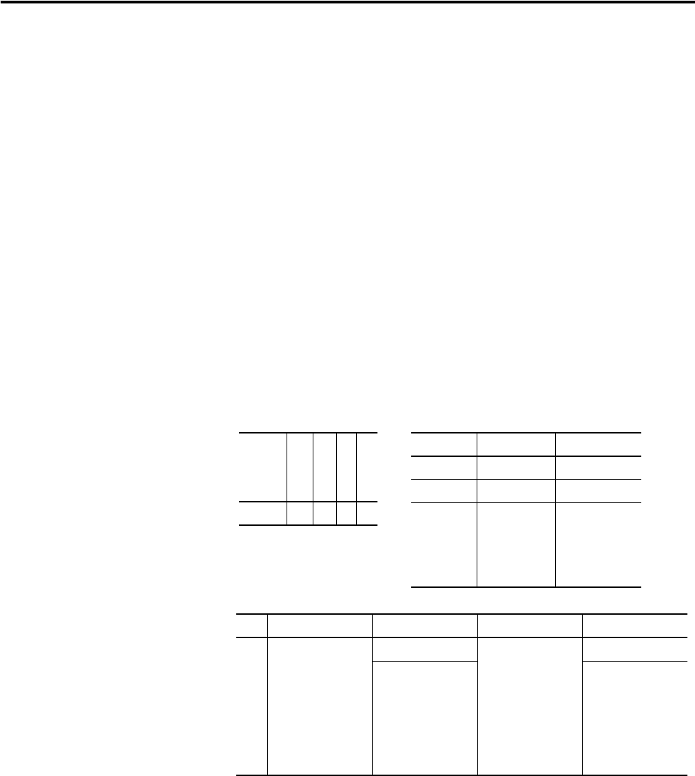
Connection Size Calculation Example
The following system will be used to demonstrate the connection size
calculation. The adapter's produced size (T
→ O) must include 8 bytes if the
optional status header is included. In some software the consumed size
(O
→T) does not need to account for the 4 byte Run/Idle header as it is
assumed and already included. For the example both header sizes have been
included.
POINT I/O system example
T → O alignment T → O size O → T alignment O → T size
1 Byte 16 bytes Byte 5 bytes
status 8 bytes
slot 1 byte
slot 2 int
slot 2 int
slot 2 byte
slot 2 byte
slot 3 byte
run /idle 4 bytes
slot 3 byte
Cat # A
E
N
T
I
B
8
I
E
2
C
O
B
4
E
Slot # 0 1 2 3
Module Tx size Rx size
IB8 1 – byte 0
OB4E 1 – byte 1 – byte
IE2C 6
- int
- int
- byte
- byte
0