
Assembly Connections for POINT I/O and ArmorPOINT I/O EtherNet/IP Adapters User Manual
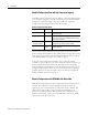
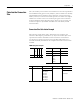
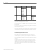
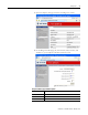

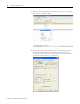
Table Of Contents
- 1734-UM016A-EN-P Assembly Connections for POINT I/O and ArmorPOINT I/O EtherNet/IP Adapters User Manual
- Important User Information
- Table of Contents
- Preface
- Chapter 1 - Introduction
- Chapter 2 - Configuration
- Chapter 3 - Using an Assembly Connection
- Chapter 4 - Assembly Structure
- Chapter 5 - 1734/1738 I/O Module Assembly Information
- Module Assembly Information
- Module Specific Details
- Two-channel Discrete Input Modules
- Four-channel Discrete Input Modules
- Eight-channel Discrete Input Modules
- Two-channel Discrete Output Modules with Status
- Two-channel Discrete Output Modules
- Four-channel Discrete Output Modules with Status
- Four-channel Discrete Output Modules
- Eight-channel Discrete Output Modules with Status
- Eight-channel Discrete Output Modules
- Four-channel Discrete Diagnostic Input Modules
- Two-channel Relay and AC Output Modules
- Four-channel Relay and AC Output Modules
- Sixteen-channel Discrete Diagnostic Input Modules
- Sixteen-channel Discrete Output Modules
- Eight-channel Configurable Discrete Input/Output Modules
- Very High Speed Counter Modules
- Counter Modules
- Two-channel Analog Input Modules
- Four-channel Analog Input Modules
- Eight-channel Analog Input Modules
- Two-channel Analog Output Modules
- Four-channel Analog Output Modules
- Two-channel RTD Input Modules
- Two-channel Thermocouple Input Modules
- Synchronous Serial Interface Modules
- Address Reserve Module
- ASCII Interface Modules
- Index
- Back Cover

Publication 1734-UM016A-EN-P - October 2010
6 Configuration
Data Alignment
Some computing devices require data to be aligned on boundaries that are
proper for their data type. There are several alignment options available to
reduce or prevent shifting operations in the originator:
Byte Boundaries
Each node's I/O data is mapped at the next available byte. Byte data can
appear at any address.
Word Boundaries
If a node's I/O data is one byte in length, it is mapped at the next available
byte. Otherwise the previous data is padded so that the node's data starts on a
16-bit boundary.
Double Word Boundaries
If a node's I/O data is one byte in length, it is mapped at the next available
byte. If a node's data is two bytes in length, padding is added to ensure that it is
mapped to an even address. If a node's data is greater than 2 bytes in length,
padding is added to ensure that the data is mapped to a Double Word
boundary.
Fixed Boundaries
The fixed boundary allows you to choose the fixed "size per slot" that each
module occupies in the I/O data. Mapping size ranges from 1…24 bytes.
The alignment choices are independently selected for each direction; O → T
and T
→ O. If Fixed Boundaries are selected, the Size per Slot choice
determines how many bytes are reserved for each slot in the I/O packet. If the
size selected is larger than a module's data, that module's data is padded with
0's out to the size selected. If the size selected is smaller than a module's data,
that module's data is truncated at the size selected.
TIP
This does not mean that every slot occupies two bytes in the image.
Word data can only begin on even addresses, for example, 0, 2, 4, 8,
0xA, or 0xC.
TIP
This does not mean that every slot occupies 4 bytes in the image.
Double Word data and array data larger than 2 bytes in size must be
aligned on addresses ending in 0, 4, 8, and 0xC.