Assembly Connections for POINT I/O and ArmorPOINT I/O EtherNet/IP Adapters Catalog Numbers Bulletins 1734 and 1738 User Manual
Important User Information Solid state equipment has operational characteristics differing from those of electromechanical equipment. Safety Guidelines for the Application, Installation and Maintenance of Solid State Controls (publication SGI-1.1 available from your local Rockwell Automation sales office or online at http://literature.rockwellautomation.com) describes some important differences between solid state equipment and hard-wired electromechanical devices.
Table of Contents Table of Contents Preface Why Read This Manual . . . . . . . . . . . . . . . . . . . . . . . . . . . . . . . . . . . . . . v Who Should Use This Manual. . . . . . . . . . . . . . . . . . . . . . . . . . . . . . . . . v About the Vocabulary . . . . . . . . . . . . . . . . . . . . . . . . . . . . . . . . . . . . . . . v Related Documentation. . . . . . . . . . . . . . . . . . . . . . . . . . . . . . . . . . . v Common Techniques Used in this Manual. . . . . . . . . . . . . . . . . . . . . .
iv Table of Contents Four-channel Discrete Input Modules . . . . . . . . . . . . . . . . . . . . . . 35 Eight-channel Discrete Input Modules. . . . . . . . . . . . . . . . . . . . . . 35 Two-channel Discrete Output Modules with Status . . . . . . . . . . . 37 Two-channel Discrete Output Modules . . . . . . . . . . . . . . . . . . . . . 38 Four-channel Discrete Output Modules with Status . . . . . . . . . . . 38 Four-channel Discrete Output Modules. . . . . . . . . . . . . . . . . . . . .
Preface Read this preface to familiarize yourself with the rest of the manual. It provides information concerning: • the purpose of this manual • related documentation • conventions used in this manual Why Read This Manual This manual is a reference guide for using Assembly Connections with POINT I/O and ArmorPOINT I/O modules. Who Should Use This Manual You must be able to program and configure industrial automation controllers and I/O to use the connections specified in this manual.
vi Preface Resource Description POINT I/O and ArmorPOINT I/O module publications Publications for POINT I/O and ArmorPOINT I/O modules are available from the Rockwell Automation Literature Library. National Electrical Code - Published by the National Fire Protection Association of Boston, MA. An article on wire sizes and types for grounding electrical equipment. You can view or download publications at http://www.literature.rockwellautomation.com.
Chapter 1 Introduction About Assembly Connections This document describes Assembly connections, a new connection type for POINT I/O and ArmorPOINT I/O EtherNet/IP adapters. These adapters currently support Rack Optimized connections between ControlLogix or CompactLogix controllers and the discrete I/O modules in the chassis. They are also capable of bridging direct connections between any EtherNet/IP-capable connection originator and the I/O modules, via the backplane.
2 Introduction Data Headers In the Target to Originator (T → O) direction, the adapter can be configured to produce a status header for the connection. The header consists of an 8-byte bitmap, where bits 1 - 63 indicate the health of each of the 63 possible backplane connections. This is similar to existing Rack Optimized connections. A "1" indicates that a module is not connected or that slot is not populated. A "0" indicates that the module is actively participating in the connection.
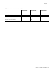
Introduction 3 Supported Connection Points for Connection Styles Connection Configuration Connection Point Consumed Connection Point Produced Connection Point Exclusive Owner 102 100 101 Listen-only 102 191 101 Input-only 102 190 101 Owning with no status header 102 100 103 Listen-only with no status header 102 191 103 Input-only with no status header 102 190 103 Publication 1734-UM016A-EN-P - October 2010
4 Introduction Notes: Publication 1734-UM016A-EN-P - October 2010
Chapter 2 Configuration About This Chapter This chapter describes the various configuration options that you can use to set up assembly connections. Configure the Connection This connection is accepted with or without a configuration assembly present. If a configuration assembly is present, it must contain the following minimum information.
6 Configuration Data Alignment Some computing devices require data to be aligned on boundaries that are proper for their data type. There are several alignment options available to reduce or prevent shifting operations in the originator: Byte Boundaries Each node's I/O data is mapped at the next available byte. Byte data can appear at any address. Word Boundaries If a node's I/O data is one byte in length, it is mapped at the next available byte.
Configuration 7 When Fixed Boundaries are selected, the formula for mapping is: H+(N-1)(size per slot), where N = slot position and H is the size of the optional status header (8 if used, 0 if not used). The choice of alignment is highly dependent on the originator used and application-specific requirements. • If data size is at a premium, Byte alignment is the most efficient choice.
8 Configuration Module Configuration Sent with the Connection Request Individual module configuration must be manually constructed and appended to the minimal configuration assembly specified in the table Minimal Adapter Configuration Assembly on page 5. For each module that needs to be configured, the following information must be provided: Module Configuration Information Field Data Type Description Slot number USINT The slot number to identify modules that require configuration data.
Configuration Calculate the Connection Size 9 The I/O assembly size is limited to the maximum size that can be specified in the standard Forward_Open service (509 bytes). The size needs to be manually calculated based on the alignment choices, inclusion of the optional status header, and the I/O sizes for the modules present in the chassis. The adapter validates the connection size in the forward open against what it calculates from the backplane and the alignment choice.
10 Configuration 2 T → O alignment T → O size O → T alignment O → T size Double Word Double Word 19 bytes run / idle 4 bytes slot 3 byte status 8 bytes slot 1 byte slot 1 pad slot 1 pad slot 1 pad slot 2 int slot 2 int slot 2 byte slot 2 byte slot 3 byte 3 6 bytes per slot 26 bytes 5 bytes 1 byte per slot status 8 bytes slot 1 6 bytes slot 2 6 bytes slot 3 6 bytes 7 bytes run /idle 4 bytes slot 1 byte slot 2 byte slot 3 byte In row 1, the data is packed on byte boundaries.
Configuration 11 1. Open the adapter's web page and select the Diagnostics folder. 2. On the Diagnostic Messaging tab, enter the Slot, Class, Instance, and Attribute to get the adapter's calculated connection sizes.
12 Configuration Diagnostic Messaging Field Description Field Description Instance 100 (O → T data) 101 (T → O data with status) 103 (T → O data without status) Attribute 4 Response 8E 00 00 00 xx xx 8E 00 — Indicates message was processed successfully 00 00 — 0 = success. Non-zero indicates an error code xx xx — Indicates size (Little Endian format)(1) (1) in Little Endian format, the least significant byte is shown first.
Chapter 3 Using an Assembly Connection Use an Assembly Connection with RSNetWorx for EtherNet/IP This section provides an illustration of the steps needed to configure the Assembly connection using RSNetWorx for EtherNet/IP. 1. Browse the EtherNet/IP network. 2. Select the connection originator that will make the connection to the 1734-AENT. Right click that device and select Scanlist Configuration to launch the Scanlist Configuration tool.
14 Using an Assembly Connection 3. Right click the targeted adapter and select Insert Connection to display the Connection Properties dialog. 4. On the Connection tab of this dialog, select the connection from the Connection Name pull-down (for example, Exclusive Owner and Listen-Only connections). Listen-Only connections are only accepted if an Exclusive Owner connection already exists.
Using an Assembly Connection 15 You can also select the Requested Packet Interval and connection sizes. For a full discussion on connections sizes, refer to the Configuration Setting tab step that follows and Calculate the Connection Size. The defaults reflect an empty system (with the adapter only). TIP In RSNetWorx, the 4-byte Run/Idle header is not considered when calculating the Output Size. When you enter the connection size on this dialog, make sure to subtract 4 bytes from your calculated size.
16 Using an Assembly Connection 6. The Configuration Setting tab displays the configuration options for the connection. Here, you can specify the Chassis Size and Data Alignment. The terms T2O and O2T are abbreviations for Target to Originator and Originator to Target. TIP Remember when specifying the Chassis Size to include 1 for the adapter. See Data Alignment for alignment choices.
Using an Assembly Connection 17 Add the Hardware to the I/O Configuration Tree 1. Add a new module to the Ethernet network in the I/O Configuration section of the Controller Organizer pane. 2. Select a Generic Ethernet Module.
18 Using an Assembly Connection Enter the Connection Parameters In the New Module Properties dialog, enter Connection Parameters, the Comm Format, the module's IP Address, and a name. Enter a Name for the module that RSLogix 5000 uses in the tags that are created for this module. The Data - SINT Comm Format should be selected, indicating that all sizes are to be interpreted as a number of bytes.
Using an Assembly Connection 19 Controller Tags by right-clicking the Controller Tags option from the Controller Organizer pane. Select Monitor Tags. Monitor Tags You should see three Tags with the module's name. They will have an C, I, or O suffix denoting Configuration, Input, or Output respectively. Note that the I and O Tags are sized according to the sizes that were entered on the properties page. The C Tag always has 400 bytes allocated for it regardless of the size specified.
20 Using an Assembly Connection and consumed alignment choice is Double Word alignment which is enumerated as a 4. See the following table for valid alignment values. Alignment choices for configuration header Alignment Choice Value Byte 0 Word 2 Double Word 4 Fixed size per slot 0xFF Add I/O Module Configuration If individual module configuration is required, it can be appended to the configuration header. In the example shown below a 1734-OB4E module is being configured.
Using an Assembly Connection 21 For more information on configuration, see 1734/1738 I/O Module Assembly Information. After the configuration has been entered into the tag, remember to save the RSLogix 5000 project. The tags are only retained upon a save. Also remember that any configuration added here must be reflected in the Configuration Size of the Connection Parameters entered on the Module Properties dialog.
22 Using an Assembly Connection The error shown above was created by entering an invalid configuration assembly size on the Module Properties page. A size of 18 bytes was entered. The error here points to an offset of 0x000b (11 decimal). If we return to the configuration tag, byte 0x000b is the location that contains the size of the I/O module configuration. The header is 10 bytes and the module has 8 bytes of configuration.
Chapter 4 Assembly Structure Assembly Structure Examples Byte, Word, and Double Word Alignment The following chassis is used to demonstrate how the data is aligned for the Byte, Word, and Double Word alignment options. This chassis was intentionally assembled as shown to demonstrate as many use cases as possible. Discrete and analog modules are intermixed. An ARM module is used to reserve space for a future device.
24 Assembly Structure Produced Assembly, Byte Aligned Byte Bit 7 Bit 6 Bit5 Bit 4 Bit 3 Bit 2 Bit 1 Bit 0 Produce 15 Slot 8 Bit 7 Slot 8 Bit 6 Slot 8 Bit 5 Slot 8 Bit 4 Slot 8 Bit 3 Slot 8 Bit 2 Slot 8 Bit 1 Slot 8 Bit 0 Produce 16 Slot 8 Bit 15 Slot 8 Bit 14 Slot 8 Bit 13 Slot 8 Bit 12 Slot 8 Bit 11 Slot 8 Bit 10 Slot 8 Bit 9 Slot 8 Bit 8 Produce 17 Slot 9 Channel 0 - Low Byte Produce 18 Slot 9 Channel 0 - High Byte Produce 19 Slot 9 Channel 1 - Low Byte Produce 20 Slot
Assembly Structure 25 Produced Assembly, Word Aligned Byte Bit 7 Bit 6 Bit5 Bit 4 Bit 3 Bit 2 Bit 1 Bit 0 Produce 0 Slot 7 status Slot 6 status Slot 5 status Slot 4 status Slot 3 status Slot 2 status Slot1 status Slot 0 status Produce 1 Slot 15 status Slot 14 status Slot 13 status Slot 12 status Slot 11 status Slot 10 status Slot 9 status Slot 8 status Produce 2 Slot 23 status Slot 22 status Slot 21 status Slot 20 status Slot 19 status Slot 18 status Slot 17 status Slot 16 status Pr
26 Assembly Structure Consumed Assembly, Word Aligned Byte Bit 7 Bit 6 Bit5 Consume 0 Reserved Consume 1 Reserved Consume 2 Reserved Consume 3 Reserved Consume 4 Reserved Consume 5 Reserved Consume 6 Slot 6 Bit 7 Consume 7 Pad Consume 8 Slot 10 ASCII Data 1 Consume 9 Slot 10 ASCII Data 2 Consume 10 Slot 10 ASCII Data 3 Consume 11 Slot 10 ASCII Data 4 Consume 12 Slot 10 ASCII Data 5 Consume 13 Slot 10 ASCII Data End of String Delimiter Consume 14 Reserved Bit 4 Bit 3 Bit
Assembly Structure 27 Produced Assembly, Double Word Aligned Byte Bit 7 Bit 6 Bit5 Bit 4 Bit 3 Bit 2 Bit 1 Bit 0 Produce 17 Slot 8 Bit 15 Slot 8 Bit 14 Slot 8 Bit 13 Slot 8 Bit 12 Slot 8 Bit 11 Slot 8 Bit 10 Slot 8 Bit 9 Slot 8 Bit 8 Produce 18 Pad Produce 19 Pad Produce 20 Slot 9 Channel 0 - Low Byte Produce 21 Slot 9 Channel 0 - High Byte Produce 22 Slot 9 Channel 1 - Low Byte Produce 23 Slot 9 Channel 1 - High Byte Produce 24 Slot 9 Channel 0 - Status Produce 25 Slot 9
28 Assembly Structure Consumed Assembly, Double Word Aligned Byte Bit 7 Bit 6 Bit5 Bit 4 Consume 11 Slot 10 ASCII Data 4 Consume 12 Slot 10 ASCII Data 5 Consume 13 Slot 10 ASCII Data End of String Delimiter Consume 14 Reserved Bit 3 Bit 2 Bit 1 Bit 0 Slot 12 Bit 3 Slot 12 Bit 2 Slot 12 Bit 1 Slot 12 Bit 0 Fixed Size per Slot Alignment The following chassis is used to demonstrate how the Fixed Size per Slot alignment option might be used.
Assembly Structure 29 Produced Assembly, Fixed Size per Slot Alignment Byte Bit 7 Produce 14 Slot 2 Channel 0 - Low Byte Produce 15 Slot 2 Channel 0 - High Byte Produce 16 Slot 2 Channel 1 - Low Byte Produce 17 Slot 2 Channel 1 - High Byte Produce 18 Slot 2 Channel 0 - Status Produce 19 Slot 2 Channel 1 - Status Produce 20 Slot 3 Channel 0 - Low Byte Produce 21 Slot 3 Channel 0 - High Byte Produce 22 Slot 3 Channel 1 - Low Byte Produce 23 Slot 3 Channel 1 - High Byte Produce 24 Slot
30 Assembly Structure Produced Assembly, Fixed Size per Slot Alignment Byte Bit 7 Produce 52 Pad Produce 53 Pad Produce 54 Pad Produce 55 Pad Bit 6 Publication 1734-UM016A-EN-P - October 2010 Bit5 Bit 4 Bit 3 Bit 2 Bit 1 Bit 0
Chapter 5 1734/1738 I/O Module Assembly Information Module Assembly Information Discrete Modules POINT I/O and ArmorPOINT I/O Discrete I/O modules Cat.
32 1734/1738 I/O Module Assembly Information POINT I/O and ArmorPOINT I/O Discrete I/O modules Cat.
1734/1738 I/O Module Assembly Information 33 POINT and ArmorPOINT Analog and Specialty I/O modules Cat.
34 1734/1738 I/O Module Assembly Information TagName TabName[High Byte] Layout for Array data: TagName[0] TagName[1] TagName[2] : : TabName[N] Module Specific Details Two-channel Discrete Input Modules All two-channel discrete input modules use the same configuration and input assemblies.
1734/1738 I/O Module Assembly Information 35 Four-channel Discrete Input Modules All four channel discrete input modules use the same configuration and input assemblies.
36 1734/1738 I/O Module Assembly Information • 1734-IB8 or 1738-IB8 • 1734-IV8 or 1738-IV8 Configuration Assembly Instance 103 Publication 1734-UM016A-EN-P - October 2010 Byte Bit 7 Bit 6 Bit 5 Bit 4 0 Input 0 Off to On Filter Low Byte 1 Input 0 Off to On Filter High Byte 2 Input 0 On to Off Filter Low Byte 3 Input 0 On to Off Filter High Byte 4 Input 1 Off to On Filter Low Byte 5 Input 1 Off to On Filter High Byte 6 Input 1 On to Off Filter Low Byte 7 Input 1 On to Off Filter High
1734/1738 I/O Module Assembly Information 37 Produced Input Data Assembly 4 Byte Bit 7 Bit 6 Bit 5 Bit 4 Bit 3 Bit 2 Bit 1 Bit 0 0 Ch 7 Ch 6 Ch 5 Ch 4 Ch 3 Ch 2 Ch 1 Ch 0 Two-channel Discrete Output Modules with Status All two-channel "enhanced" discrete output modules use the same configuration and I/O assemblies.
38 1734/1738 I/O Module Assembly Information Two-channel Discrete Output Modules Use the tables shown below for the following modules: • 1734-OB2 or 1738-OB2 Configuration Assembly Instance 123 Byte Bit 7 0 Bit 6 Bit 5 Bit 4 Bit 3 Bit 2 Bit 1 Bit 0 Reserved Fault State 1 Fault State 0 1 Reserved Fault Value 1 Fault Value 0 2 Reserved Idle State 1 Idle State 0 3 Reserved Idle Value 1 Idle Value 0 4 Reserved (Set to 0) 5 Reserved (Set to 0) 6 Reserved (Set to 0) 7 Pad Produc
1734/1738 I/O Module Assembly Information 39 Configuration Assembly Instance 123 Byte Bit 7 0 Bit 6 Bit 5 Bit 4 Bit 3 Bit 2 Bit 1 Bit 0 Reserved Fault State 3 Fault State 2 Fault State 1 Fault State 0 1 Reserved Fault Value 3 Fault Value 2 Fault Value 1 Fault Value 0 2 Reserved Idle State 3 Idle State 2 Idle State 1 Idle State 0 3 Reserved Idle Value 3 Idle Value 2 Idle Value 1 Idle Value 0 4 Reserved Enable No Load 3 Enable No Load 2 Enable No Load 1 Enable No Load 0 5
40 1734/1738 I/O Module Assembly Information Produced Input Data Assembly 43 Byte Bit 7 0 Reserved Bit 6 Bit 5 Bit 4 Bit 3 Bit 2 Bit 1 Bit 0 Bit 4 Bit 3 Bit 2 Bit 1 Bit 0 Ch 3 Ch 2 Ch 1 Ch 0 Consumed Output Data Assembly 33 Byte Bit 7 0 Reserved Bit 6 Bit 5 Eight-channel Discrete Output Modules with Status All eight-channel "enhanced" discrete output modules use the same configuration and I/O assemblies.
1734/1738 I/O Module Assembly Information 41 Eight-channel Discrete Output Modules Use the tables shown below for the following modules: • 1734-OB8 or 1738-OB8 Configuration Assembly Instance 123 Byte Bit 7 Bit 6 Bit 5 Bit 4 Bit 3 Bit 2 Bit 1 Bit 0 0 Fault State 7 Fault State 6 Fault State 5 Fault State 4 Fault State 3 Fault State 2 Fault State 1 Fault State 0 1 Fault Value 7 Fault Value 6 Fault Value 5 Fault Value 4 Fault Value 3 Fault Value 2 Fault Value 1 Fault Value 0 2 Id
42 1734/1738 I/O Module Assembly Information Configuration Assembly Instance 103 Byte Bit 7 Bit 6 0 Input 0 Off to On Filter Low Byte 1 Input 0 Off to On Filter High Byte 2 Input 0 On to Off Filter Low Byte 3 Input 0 On to Off Filter High Byte 4 Input 1 Off to On Filter Low Byte 5 Input 1 Off to On Filter High Byte 6 Input 1 On to Off Filter Low Byte 7 Input 1 On to Off Filter High Byte 8 Input 2 Off to On Filter Low Byte 9 Input 2 Off to On Filter High Byte 10 Input 2 On to Off Fi
1734/1738 I/O Module Assembly Information 43 Two-channel Relay and AC Output Modules All two-channel relay and AC output modules use the same Consumed I/O assembly. There are no Produced or Configuration assemblies for these modules.
44 1734/1738 I/O Module Assembly Information Configuration Assembly Instance 103 Byte Bit 7 Bit 6 Bit 5 Bit 4 0 Input Off to On Filter Low Byte 1 Input Off to On Filter High Byte 2 Input On to Off Filter Low Byte 3 Input On to Off Filter High Byte 4 Produced Assembly 5 Reserved = 0 Bit 3 Bit 2 Bit 1 Bit 0 This POINT I/O input module produces 2 or 3 bytes of input data based on which produced assembly is selected. The default assembly instance 101 is 3 bytes.
1734/1738 I/O Module Assembly Information 45 Produced Diagnostic Data Assembly 101 Byte Bit 7 0 Reserved Bit 6 Bit 5 Bit 4 Bit 3 Bit 2 Bit 1 Bit 0 Fault LED State Fault 12…15 Fault 8…11 Fault 4…7 Fault 0…3 Consumed Output Data Assembly 37 Byte Bit 7 Bit 6 Bit 5 Bit 4 Bit 3 Bit 2 Bit 1 Bit 0 0 Ch 7 Ch 6 Ch 5 Ch 4 Ch 3 Ch 2 Ch 1 Ch 0 1 Ch 15 Ch 14 Ch 13 Ch 12 Ch 11 Ch 10 Ch 9 Ch 8 Eight-channel Configurable Discrete Input/Output Modules All eight channel "configura
46 1734/1738 I/O Module Assembly Information Consumed Output Data Assembly 34 Byte Bit 7 Bit 6 Bit 5 Bit 4 Bit 3 Bit 2 Bit 1 Bit 0 0 Ch 7 Ch 6 Ch 5 Ch 4 Ch 3 Ch 2 Ch 1 Ch 0 Very High Speed Counter Modules Use the tables shown below for the following modules: • 1734-VHSC5 • 1734-VHSC25 or 1738-VHSC24M23 The modules support 3 different consumed output data assemblies. The Active Output Assembly field of the Configuration assembly selects which output assembly will be used.
1734/1738 I/O Module Assembly Information 47 Consumed Output Data Assembly 107 Byte Bit 7 Bit 6 Bit 5 0 PWM Value (Low Byte) 1 PWM Value (High Byte) 2 Counter Control 3 Output Control Bit 4 Bit 3 Bit 2 Bit 1 Bit 0 Bit 4 Bit 3 Bit 2 Bit 1 Bit 0 Configuration Assembly Instance 108 Byte Bit 7 Bit 6 Bit 5 0 Counter Configuration 1 Filter Selection 2 Decimal Position 3 Active Output Assembly 4 Time Base or PWM Period (low byte) 5 Time Base or PWM Period (high byte) 6 Gate
48 1734/1738 I/O Module Assembly Information Configuration Assembly Instance 108 Byte Bit 7 Bit 6 Bit 5 Bit 4 29 ON Value # 2 [High Byte] 30 OFF Value #2 [Low Byte] 31 OFF Value #2 [1] 32 OFF Value #2 [2] 33 OFF Value #2 [High Byte] 34 ON Value # 3 [Low Byte] 35 ON Value # 3 [1] 36 ON Value # 3 [2] 37 ON Value # 3 [High Byte] 38 OFF Value #3 [Low Byte] 39 OFF Value #3 [1] 40 OFF Value #3 [2] 41 OFF Value #3 [High Byte] 42 ON Value # 4 [Low Byte] 43 ON Value # 4 [1] 44 O
1734/1738 I/O Module Assembly Information 49 default produced assembly. For more information regarding the specific fields of these assemblies, consult the product's user manual.
50 1734/1738 I/O Module Assembly Information Two-channel Analog Input Modules Use the tables shown below for the following modules: • 1734-IE2C • 1734-IE2V • 1738-IE2CM12 or 1738-IE2VM12 Configuration Assembly Instance 123 Publication 1734-UM016A-EN-P - October 2010 Byte Bit 7 Bit 6 Bit 5 Bit 4 0 Low Engineering Channel 0 (Low Byte) 1 Low Engineering Channel 0 (High Byte) 2 High Engineering Channel 0 (Low Byte) 3 High Engineering Channel 0 (High Byte) 4 Digital Filter Channel 0 (Low Byte)
1734/1738 I/O Module Assembly Information 51 Configuration Assembly Instance 123 Byte Bit 7 Bit 6 Bit 5 Bit 4 27 High Alarm Channel 1 (High Byte) 28 Low Low Alarm Channel 1 (Low Byte) 29 Low Low Alarm Channel 1 (High Byte) 30 High High Alarm Channel 1 (Low Byte) 31 High High Alarm Channel 1 (High Byte) 32 Range Channel 1 33 Alarm Latch Channel 1 34 Alarm Disable Channel 1 35 Notch Filter 36 Update Rate (Low Byte) 37 Update Rate (High Byte) Bit 3 Bit 2 Bit 1 Bit 0 Bit 3 Bit
52 1734/1738 I/O Module Assembly Information Configuration Assembly Instance 123 Publication 1734-UM016A-EN-P - October 2010 Byte Bit 7 Bit 6 Bit 5 Bit 4 5 Digital Filter Channel 0 (High Byte) 6 Low Alarm Channel 0 (Low Byte) 7 Low Alarm Channel 0 (High Byte) 8 High Alarm Channel 0 (Low Byte) 9 High Alarm Channel 0 (High Byte) 10 Low Low Alarm Channel 0 (Low Byte) 11 Low Low Alarm Channel 0 (High Byte) 12 High High Alarm Channel 0 (Low Byte) 13 High High Alarm Channel 0 (High Byte)
1734/1738 I/O Module Assembly Information 53 Configuration Assembly Instance 123 Byte Bit 7 Bit 6 Bit 5 Bit 4 Bit 3 41 Digital Filter Channel 2 (High Byte) 42 Low Alarm Channel 2 (Low Byte) 43 Low Alarm Channel 2 (High Byte) 44 High Alarm Channel 2 (Low Byte) 45 High Alarm Channel 2 (High Byte) 46 Low Low Alarm Channel 2 (Low Byte) 47 Low Low Alarm Channel 2 (High Byte) 48 High High Alarm Channel 2 (Low Byte) 49 High High Alarm Channel 2 (High Byte) 50 Range Channel 2 51 Alarm L
54 1734/1738 I/O Module Assembly Information Produced Input Data Assembly 101 Byte Bit 7 Bit 6 Bit 5 0 Channel 0 Data (Low Byte) 1 Channel 0 Data (High Byte) 2 Channel 1 Data (Low Byte) 3 Channel 1 Data (High Byte) 4 Channel 2 Data (Low Byte) 5 Channel 2 Data (High Byte) 6 Channel 3 Data (Low Byte) 7 Channel 3 Data (High Byte) 8 Channel 0 Status 9 Channel 1 Status 10 Channel 2 Status 11 Channel 3 Status Bit 4 Bit 3 Bit 2 Bit 1 Bit 0 Bit 1 Bit 0 Eight-channel Analog Input
1734/1738 I/O Module Assembly Information 55 Configuration Assembly Instance 123 Byte Bit 7 Bit 6 Bit 5 Bit 4 Bit 3 12 High High Alarm Channel 0 (Low Byte) 13 High High Alarm Channel 0 (High Byte) 14 Range Channel 0 15 Alarm Latch Channel 0 16 Alarm Disable Channel 0 17 Alignment (reserved = 0) 18 Low Engineering Channel 1 (Low Byte) 19 Low Engineering Channel 1 (High Byte) 20 High Engineering Channel 1 (Low Byte) 21 High Engineering Channel 1 (High Byte) 22 Digital Filter Chann
56 1734/1738 I/O Module Assembly Information Configuration Assembly Instance 123 Publication 1734-UM016A-EN-P - October 2010 Byte Bit 7 Bit 6 Bit 5 Bit 4 48 High High Alarm Channel 2 (Low Byte) 49 High High Alarm Channel 2 (High Byte) 50 Range Channel 2 51 Alarm Latch Channel 2 52 Alarm Disable Channel 2 53 Alignment (reserved = 0) 54 Low Engineering Channel 3 (Low Byte) 55 Low Engineering Channel 3 (High Byte) 56 High Engineering Channel 3 (Low Byte) 57 High Engineering Channel
1734/1738 I/O Module Assembly Information 57 Configuration Assembly Instance 123 Byte Bit 7 Bit 6 Bit 5 Bit 4 Bit 3 84 High High Alarm Channel 4 (Low Byte) 85 High High Alarm Channel 4 (High Byte) 86 Range Channel 4 87 Alarm Latch Channel 4 88 Alarm Disable Channel 4 89 Alignment (reserved = 0) 90 Low Engineering Channel 5 (Low Byte) 91 Low Engineering Channel 5 (High Byte) 92 High Engineering Channel 5 (Low Byte) 93 High Engineering Channel 5 (High Byte) 94 Digital Filter Chann
58 1734/1738 I/O Module Assembly Information Configuration Assembly Instance 123 Byte Bit 7 Bit 6 Bit 5 Bit 4 120 High High Alarm Channel 6 (Low Byte) 121 High High Alarm Channel 6 (High Byte) 122 Range Channel 6 123 Alarm Latch Channel 6 124 Alarm Disable Channel 6 125 Alignment (reserved = 0) 126 Low Engineering Channel 7 (Low Byte) 127 Low Engineering Channel 7 (High Byte) 128 High Engineering Channel 7 (Low Byte) 129 High Engineering Channel 7 (High Byte) 130 Digital Filter C
1734/1738 I/O Module Assembly Information 59 Produced Input Data Assembly 101 Byte Bit 7 Bit 6 Bit 5 8 Channel 4 Data (Low Byte) 9 Channel 4 Data (High Byte) 10 Channel 5 Data (Low Byte) 11 Channel 5 Data (High Byte) 12 Channel 6 Data (Low Byte) 13 Channel 6 Data (High Byte) 14 Channel 7 Data (Low Byte) 15 Channel 7 Data (High Byte) 16 Channel 0 Status 17 Channel 1 Status 18 Channel 2 Status 19 Channel 3 Status 20 Channel 4 Status 21 Channel 5 Status 22 Channel 6 Status 2
60 1734/1738 I/O Module Assembly Information Configuration Assembly Instance 123 Byte Bit 7 Bit 6 Bit 5 Bit 4 7 High Engineering Channel 0 (High Byte) 8 Low Clamp Channel 0 (Low Byte) 9 Low Clamp Channel 0 (High Byte) 10 High Clamp Channel 0 (Low Byte) 11 High Clamp Channel 0 (High Byte) 12 Range Channel 0 13 Fault Action Channel 0 14 Idle Action Channel 0 15 Alarm Latch Channel 0 16 Alarm Disable Channel 0 17 Alignment (reserved = 0) 18 Fault Data Channel 1 (Low Byte) 19 Fau
1734/1738 I/O Module Assembly Information 61 Consumed Output Data Assembly 102 Byte Bit 7 Bit 6 Bit 5 0 Channel 0 Data (Low Byte) 1 Channel 0 Data (High Byte) 2 Channel 1 Data (Low Byte) 3 Channel 1 Data (High Byte) Bit 4 Bit 3 Bit 2 Bit 1 Bit 0 Bit 1 Bit 0 Four-channel Analog Output Modules Use the tables shown below for the following modules: • 1734-OE4C • 1738-OE4CM12 or 1738-OE4VM12 Configuration Assembly Instance 123 Byte Bit 7 Bit 6 Bit 5 Bit 4 Bit 3 0 Fault Data Channel 0
62 1734/1738 I/O Module Assembly Information Configuration Assembly Instance 123 Publication 1734-UM016A-EN-P - October 2010 Byte Bit 7 Bit 6 Bit 5 Bit 4 20 Idle Data Channel 1 (Low Byte) 21 Idle Data Channel 1 (High Byte) 22 Low Engineering Channel 1 (Low Byte) 23 Low Engineering Channel 1 (High Byte) 24 High Engineering Channel 1 (Low Byte) 25 High Engineering Channel 1 (High Byte) 26 Low Clamp Channel 1 (Low Byte) 27 Low Clamp Channel 1 (High Byte) 28 High Clamp Channel 1 (Low B
1734/1738 I/O Module Assembly Information 63 Configuration Assembly Instance 123 Byte Bit 7 Bit 6 Bit 5 Bit 4 Bit 3 Bit 2 Bit 1 Bit 0 56 Idle Data Channel 3 (Low Byte) 57 Idle Data Channel 3 (High Byte) 58 Low Engineering Channel 3 (Low Byte) 59 Low Engineering Channel 3 (High Byte) 60 High Engineering Channel 3 (Low Byte) 61 High Engineering Channel 3 (High Byte) 62 Low Clamp Channel 3 (Low Byte) 63 Low Clamp Channel 3 (High Byte) 64 High Clamp Channel 3 (Low Byte) 65 High Cla
64 1734/1738 I/O Module Assembly Information Two-channel RTD Input Modules Use the tables shown below for the following modules: • 1734-IR2 • 1734-IR2E or 1738-IR2M12 Configuration Assembly Instance 123 Publication 1734-UM016A-EN-P - October 2010 Byte Bit 7 Bit 6 Bit 5 Bit 4 0 Low Engineering Channel 0 (Low Byte) 1 Low Engineering Channel 0 (High Byte) 2 High Engineering Channel 0 (Low Byte) 3 High Engineering Channel 0 (High Byte) 4 Digital Filter Channel 0 (Low Byte) 5 Digital Filter
1734/1738 I/O Module Assembly Information 65 Configuration Assembly Instance 123 Byte Bit 7 Bit 6 Bit 5 Bit 4 28 Low Low Alarm Channel 1 (Low Byte) 29 Low Low Alarm Channel 1 (High Byte) 30 High High Alarm Channel 1 (Low Byte) 31 High High Alarm Channel 1 (High Byte) 32 Alarm Latch Channel 1 33 Alarm Disable Channel 1 34 Sensor Type Channel 1 35 Temperature Units Channel 1 36 Notch Filter 37 Alignment (reserved = 0) Bit 3 Bit 2 Bit 1 Bit 0 Bit 3 Bit 2 Bit 1 Bit 0 Bit 1 Bi
66 1734/1738 I/O Module Assembly Information Configuration Assembly Instance 103 Publication 1734-UM016A-EN-P - October 2010 Byte Bit 7 Bit 6 Bit 5 Bit 4 7 Alarm Latch Channel 0 8 Notch Filter Channel 0 9 Sensor Type Channel 0 10 Digital Filter Channel 0 (Low Byte) 11 Digital Filter Channel 0 (High Byte) 12 Low Alarm Channel 0 (Low Byte) 13 Low Alarm Channel 0 (High Byte) 14 High Alarm Channel 0 (Low Byte) 15 High Alarm Channel 0 (High Byte) 16 Low Low Alarm Channel 0 (Low Byte)
1734/1738 I/O Module Assembly Information 67 Configuration Assembly Instance 103 Byte Bit 7 Bit 6 Bit 5 Bit 4 43 Cold Junction Enable Chan 1 44 Cold Junction Offset Chan 1 (Low Byte) 45 Cold Junction Offset Chan 1 (High Byte) Bit 3 Bit 2 Bit 1 Bit 0 Bit 3 Bit 2 Bit 1 Bit 0 Bit 1 Bit 0 Produced Input Data Assembly 101 Byte Bit 7 Bit 6 Bit 5 0 Channel 0 Data (Low Byte) 1 Channel 0 Data (High Byte) 2 Channel 1 Data (Low Byte) 3 Channel 1 Data (High Byte) 4 Channel 0 Status
68 1734/1738 I/O Module Assembly Information Configuration Assembly Instance 123 Byte Bit 7 Bit 6 Bit 5 Bit 4 Bit 3 Bit 2 Bit 1 Bit 0 12 Sensor Cycles (Low Byte) 13 Sensor Cycles (High Byte) 14 SSI Word Filter Control 15 Alignment (reserved = 0) 16 Comparator 1 Value [Low Byte] 17 Comparator 1 Value [1] 18 Comparator 1 Value [2] 19 Comparator 1 Value [High Byte] 20 Comparator 2 Value [Low Byte] 21 Comparator 2 Value [1] 22 Comparator 2 Value [2] 23 Comparator 2 Value [High
1734/1738 I/O Module Assembly Information 69 Address Reserve Module Use the table shown below for the 1734-ARM. This module has no configuration and does not consume any I/O data.
70 1734/1738 I/O Module Assembly Information Configuration Assembly Instance 103 Byte Bit 7 Bit 6 Bit 5 Bit 4 15 ASCII Consume String Data Type 16 ASCII Transmit Swap Mode 17 Transmit Handshake Mode Bit 3 Bit 2 Bit 1 Bit 0 The format and length of the Produced and Consumed I/O assemblies vary with the configuration of the module. For more information regarding the specific fields of these assemblies and how they are impacted by the configuration, refer to the product user manual.
Index Numerics 16 bit numbers 33 16-bit boundary 6 1734/1738 I/O module assembly information 31 1734-ARM module 7 6 bytes 28 A AC output modules 43 two-channel 43 Active Output Assembly 46 adapter data exchange 1 add hardware 17 Address Reserve Module 28 alignment 6, 23 Byte 20, 23 Double Word 7, 10, 20, 23 Fixed Size per Slot 20, 28 option 28 Word 20, 23 alignment options 6 analog I/O modules 32 ARM module 23 Array data 34 assemblies configuration 43 data 46 I/O 37, 38, 40 input 34, 35 produced 43, 46 Ass
72 Index resolve 10 validate 10 connection tab 14 connection type 1 Consumed 43 consumed I/O assembly 43 Controller Organizer 17 pane 19 controller tags 19 option 19 ControlLogix 1 conventions vi D data alignment 6, 34 boundaries 7 exchange 1 headers 2 multi-byte 33 SINT 18 values 33 data alignment 6, 10, 16 data assemblies 46 data assembly 34 data boundaries 7 data headers 2 data structure 7 different connection styles 2 direct connections 1 discrete modules 31 discrete diagnostic input sixteen-channel
Index insert connection 14 intelligent tags 16 Invalid Connection Size 10 L layout 33 least significant byte 33 Listen-Only connections 2, 14 originators 1 little endian 20, 33 M manuals related v minimal 7 Monitor tag C tag 19 I tag 19 O tag 19 Monitor tags 19 most significant byte 33 Multicast 15 multiple originators 2 73 pane 17 Point to Point 15 Produced 43 produced assemblies 43, 46 profile EtherNet/IP 16 properties connection 14 publications related v R Rack Optimized 1 connections 1, 2 direct c
74 Index T T-->O 9 T2O 16 tag arrays unstructured 16 Target to Originator 2 troubleshooting connection size errors 10 two-channel 34, 37 discrete Input modules 34, 38, 37 relay and AC output modules 43 U unstructured tag arrays 16 V values data 33 W word 6, 23 word boundaries 6 words 15 Publication 1734-UM016A-EN-P - October 2010
Rockwell Automation Support Rockwell Automation provides technical information on the Web to assist you in using its products. At http://www.rockwellautomation.com/support/, you can find technical manuals, a knowledge base of FAQs, technical and application notes, sample code and links to software service packs, and a MySupport feature that you can customize to make the best use of these tools.