Installation Instructions ArmorPoint 24V dc Input Modules, Series A Cat. Nos. 1738-IB2M12, -IB4M8, -IB4M12, -IB8M8, -IB8M12, -IB8M23, -IV4M12, -IV8M8, -IV8M12, -IV8M23 The ArmorPoint™ I/O family consists of modular I/O modules. The sealed IP67 housing of these modules requires no enclosure. (Note that environmental requirements other than IP67 may require an additional appropriate housing.) I/O connectors are sealed M8 (pico), M12 (micro) or M23 styles. The mounting base ships with the module.
ArmorPoint 24V dc Input Modules, Series A Important User Information Solid state equipment has operational characteristics differing from those of electromechanical equipment. Safety Guidelines for the Application, Installation and Maintenance of Solid State Controls (Publication SGI-1.1 available from your local Rockwell Automation sales office or online at http://www.ab.com/manuals/gi) describes some important differences between solid state equipment and hard-wired electromechanical devices.
ArmorPoint 24V dc Input Modules, Series A ATTENTION 3 Environment and Enclosure This equipment is intended for use in overvoltage Category II applications (as defined in IEC publication 60664-1), at altitudes up to 2000 meters without derating. This equipment is considered Group 1, Class A industrial equipment according to IEC/CISPR Publication 11.
ArmorPoint 24V dc Input Modules, Series A Mount the I/O Base To mount the base on a wall or panel, use the screw holes provided in the base. IMPORTANT The module must be mounted on a grounded metal mounting plate or other conductive surface. A drilling dimensions mounting illustration for the base with an adapter is shown below. Drilling Dimensions 1.9 in. 47.2 mm Adapter 2.0 in. 50 mm 0.87 in. 22 mm 2.0 in. 50 mm 0.87 in. 22 mm 2.0 in. 50 mm 4.02 in. 102 mm 1.81 in.
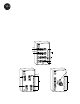
ArmorPoint 24V dc Input Modules, Series A Install the Digital Input Module 5 To install the digital input module: 1. Using a bladed screwdriver, rotate the keyswitch on the mounting base clockwise until the number 1 aligns with the notch in the base. 2. Position the module vertically above the mounting base. The module will bridge two bases. Module will bridge two bases. 1738-IB8M12/A 24V dc In 0 2 1 3 MOD NET 0 1 2 3 4 6 5 7 4 5 6 7 43772 3.
ArmorPoint 24V dc Input Modules, Series A Wire the Modules Following are wiring instructions for the modules.
ArmorPoint 24V dc Input Modules, Series A 7 1738-IB8M23 and 1738-IV8M23 1 8 9 7 2 10 12 6 3 11 4 5 43681 ATTENTION Communicate With Your Module (view into connector) Pin 1 - Input 0 Pin 2 - Input 1 Pin 3 - Input 2 Pin 4 - Input 3 Pin 5 - Input 4 Pin 6 - Input 5 Pin 7 - Input 6 Pin 8 - Input 7 Pin 9 - Return (Com) Pin 10 - Return (Com) Pin 11 - 24V dc Pin 12 - Chassis Make sure all connectors and caps are securely tightened to properly seal the connections against leaks and maintain IP67 req
ArmorPoint 24V dc Input Modules, Series A 1738-IB8M8, -IB8M12, -IB8M23, -IV8M8, -IV8M12, and -IV8M23 Modules Message size: 1 Byte Produces (Rx) 7 6 5 4 3 2 1 0 Ch7 Ch6 Ch5 Ch4 Ch3 Ch2 Ch1 Ch0 Channel status Where: 0 = off, 1 = on Troubleshoot With the Indicators 1738-IB8M12 1738-IB8M12/A 24V dc In 0 2 1 3 Module Status Indicators Network Status Indicators MOD NET 0 1 2 I/O Status Indicators 3 4 6 4 5 5 7 6 7 43680 Indication Probable Cause Module Status Publication
ArmorPoint 24V dc Input Modules, Series A Indication 9 Probable Cause Network Status Off Device is not on line: - Device has not completed dup_MAC_ID test. - Device not powered - check module status indicator. Flashing Green Device is on line but has no connections in the established state. Green Device is on line and has connections in the established state. Flashing Red One or more I/O connections in timed-out state. Red Critical link failure - failed communication device.
ArmorPoint 24V dc Input Modules, Series A ArmorPoint Digital Input Modules Input Delay Time, ON to OFF Input Point Density Field Power Bus Supply Voltage Range, Nominal Keyswitch Position General Specifications LED Indicators PointBus Current, Maximum Power Dissipation, Maximum Thermal Dissipation, Maximum Isolation Voltage (continuous-voltage withstand rating) Dimensions (includes I/O module Inches and mounting base) (Millimeters) Operating Temperature Storage Temperature Relative Humidity Shock
ArmorPoint 24V dc Input Modules, Series A General Specifications (continued) Emissions Enclosure Type Rating Mounting Base Screw Torque Weight Imperial (Metric) Wiring Category2 11 CSPR 11: Group 1, Class A Meets IP65/66/67 (when marked) #8 screw, 7.5 in. lbs. in Aluminum, 16 in. lbs. in Steel 0.64 lb. (0.
Rockwell Automation Support Rockwell Automation provides technical information on the web to assist you in using its products. At http://support.rockwellautomation.com, you can find technical manuals, a knowledge base of FAQs, technical and application notes, sample code and links to software service packs, and a MySupport feature that you can customize to make the best use of these tools.