Installation Instructions ArmorPOINT™ 24V DC Analog Output Modules Catalog numbers 1738-OE2CM12, 1738-OE2VM12, Series A Table of Contents Topic Page Important User Information 2 Environment and Enclosure 3 Prevent Electrostatic Discharge 3 About the Modules 4 Mount the I/O Base 5 Install the Module 6 Remove the Module from the Mounting Base 6 Wire the Modules 7 Communicate with the Module 8 Interpret Status Indicators 9 Specifications 11
ArmorPOINT™ 24V DC Analog Output Modules Important User Information Solid-state equipment has operational characteristics differing from those of electromechanical equipment. Safety Guidelines for the Application, Installation and Maintenance of Solid State Controls (Publication SGI-1.1 available from your local Rockwell Automation sales office or online at http://www.rockwellautomation.
ArmorPOINT™ 24V DC Analog Output Modules 3 Environment and Enclosure ATTENTION: This equipment is intended for use in overvoltage Category II applications (as defined in IEC 60664-1), at altitudes up to 2000 m (6562 ft) without derating. This equipment is considered Group 1, Class A industrial equipment according to IEC/CISPR 11. Without appropriate precautions, there may be difficulties with electromagnetic compatibility in residential and other environments due to conducted and radiated disturbances.
ArmorPOINT™ 24V DC Analog Output Modules About the Modules The ArmorPOINT I/O family consists of modular I/O modules. The sealed IP67 housing of these modules requires no enclosure. Note that environmental requirements other than IP67 may require an additional appropriate housing. I/O connectors are sealed M12 style. The mounting base ships with the module. The 1738-OE2CM12 module is shown here.
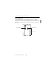
ArmorPOINT™ 24V DC Analog Output Modules 5 Mount the I/O Base To mount the base on a wall or panel, use the screw holes provided in the base. ATTENTION: The ArmorPOINT I/O module must be mounted on a grounded metal mounting plate or other conductive surface. A mounting diagram for the ArmorPOINT base with adapter is shown here. 20.1 (0.8) 20.1 (0.8) 46.25 (1.8) Millimeters 51.9 (2) 51.9 (2) 51.9 (2) (Inches) 56 (2.2) 102 (4.02) Adapter 45707 Install the mounting base as follows: 1.
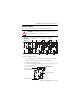
ArmorPOINT™ 24V DC Analog Output Modules Install the Module To install the analog output module, proceed as follows: 1. Using a bladed screwdriver, rotate the keyswitch on the mounting base clockwise until the number 4 aligns with the notch in the base. 2. Position the module vertically above the mounting base. The module bridges two bases. Module bridges two bases. 1738-OE2CM12/A Analog Current Out 0 1 MOD NET 0 1 45757 3. Push the module down until it engages the latching mechanism.
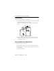
ArmorPOINT™ 24V DC Analog Output Modules 7 Wire the Modules The wiring instructions for the modules are shown here. 1738-OE2CM12, 1738-OE2VM12 (View into connector) Pin 1 Output 0 (M12-A) Output 1 (M12-B) Pin 2 24V DC Pin 3 Common Pin 4 Common Pin 5 No connect 43664 IMPORTANT Analog modules have earth grounded metal rings. This should be considered when choosing shielded cables and grounding techniques.
ArmorPOINT™ 24V DC Analog Output Modules Communicate with the Module I/O messages are sent to (consumed) and received from (produced) the ArmorPOINT modules. These messages are mapped onto the processor’s memory. The ArmorPOINT analog output modules produce 2 Bytes of input data (scanner Rx – fault status). They consume 4 Bytes of output data (scanner Tx).
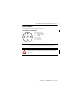
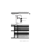
ArmorPOINT™ 24V DC Analog Output Modules 9 Interpret Status Indicators 1738-OE2CM12 1738-OE2CM12/A Analog Current Out 0 1 Module status indicator Network status indicator MOD NET 0 1 I/O status indicators 45755 Indicator Status for Modules Module status Status Description Off No power applied to device. Green Device operating normally. Flashing green Device needs commissioning due to missing, incomplete, or incorrect configuration. Flashing red Recoverable fault.
ArmorPOINT™ 24V DC Analog Output Modules Indicator Status for Modules I/O status Status Description Off Module in CAL mode. Solid green Device operating normally. Flashing green Channel being calibrated. Flashing red 1738-OE2VM12 – Low or high clamp. 1738-OE2CM12 – Open wire or no power. Solid red 1738-OE2VM12 only – No power.
ArmorPOINT™ 24V DC Analog Output Modules 11 Specifications ArmorPOINT 24V DC Analog Output Modules – 1738-OE2CM12, 1738-OE2VM12 Attribute Value Outputs per module 2 single-ended, nonisolated Output voltage 1738-OE2V 0V output until communication established 0…10V (user-configurable; 0V under, 5V over) 10V (user-configurable; -0.
ArmorPOINT™ 24V DC Analog Output Modules General Specifications Attribute Value Calibration Factory-calibrated Mounting base screw torque #8 screw 0.85 Nm (7.5 lb-in.) in aluminum 1.8 Nm (16 lb-in.) in steel Indicators 1 green/red – module status indicator, logic side 1 green/red – network status indicator, logic side 2 green/red – output status indicators, logic side Power dissipation, max @ 28.8V DC 1738-OE2C 750 Ω load on each output – 1.23 W 0 Ω load on each output – 1.83 W 1738-OE2V 1.
ArmorPOINT™ 24V DC Analog Output Modules 13 Environmental Specifications Attribute Value Temperature, operating IEC 60068-2-1 (Test Ad, Operating Cold), IEC 60068-2-2 (Test Bd, Operating Dry Heat), IEC 60068-2-14 (Test Nb, Operating Thermal Shock): -20…60 °C (-4…140 °F) Temperature, nonoperating IEC 60068-2-1 (Test Ab, Unpackaged Nonoperating Cold), IEC 60068-2-2 (Test Bb, Unpackaged Nonoperating Dry Heat), IEC 60068-2-14 (Test Na, Unpackaged Nonoperating Thermal Shock): -40…85 °C (-40…185 °F) Relat
ArmorPOINT™ 24V DC Analog Output Modules Certifications Certification (when product is marked)(1) Value CE European Union 89/336/EEC EMC Directive, compliant with: EN 50081-2; Industrial Emissions EN 50082-2; Industrial Immunity EN 61326; Meas./Control/Lab., Industrial Requirements EN 61000-6-2; Industrial Immunity EN 61000-6-4; Industrial Emissions C-Tick Australian Radiocommunications Act, compliant with: AS/NZS CISPR 11; Industrial Emissions (1) See the Product Certification link at http://www.
ArmorPOINT™ 24V DC Analog Output Modules 15 Notes: Publication 1738-IN004B-EN-E - July 2011
Rockwell Automation Support Rockwell Automation provides technical information on the Web to assist you in using its products. At http://www.rockwellautomation.com/support/, you can find technical manuals, a knowledge base of FAQs, technical and application notes, sample code and links to software service packs, and a MySupport feature that you can customize to make the best use of these tools.