Installation Instructions ArmorPOINT RTD and Thermocouple Input Modules Catalog numbers 1738-IR2M12, 1738-IT2IM12, Series A Table of Contents Topic Page Important User Information 2 Environment and Enclosure 3 Preventing Electrostatic Discharge 3 About the Module 4 Mount the I/O Base 5 Install the Module 6 Remove the Module from the Mounting Base 6 Wire the Module 7 Communicate with the Module 8 Interpret Status Indicators 10 Specifications 12
ArmorPOINT RTD and Thermocouple Input Modules Important User Information Solid-state equipment has operational characteristics differing from those of electromechanical equipment. Safety Guidelines for the Application, Installation and Maintenance of Solid State Controls (Publication SGI-1.1 available from your local Rockwell Automation sales office or online at http://www.rockwellautomation.
ArmorPOINT RTD and Thermocouple Input Modules 3 Environment and Enclosure ATTENTION: This equipment is intended for use in overvoltage Category II applications (as defined in IEC 60664-1), at altitudes up to 2000 m (6562 ft) without derating. This equipment is considered Group 1, Class A industrial equipment according to IEC/CISPR 11.
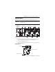
ArmorPOINT RTD and Thermocouple Input Modules About the Module The ArmorPOINT™ I/O family consists of modular I/O modules. The sealed IP67 housing of these modules requires no enclosure. Note that environmental requirements other than IP67 may require an additional appropriate housing. I/O connectors are sealed M12 (micro) style. The mounting base ships with the module. The 1738-IR2M12 module is shown here.
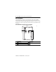
ArmorPOINT RTD and Thermocouple Input Modules 5 Mount the I/O Base Mount the I/O base on a wall or panel, using the screw holes provided in the base. The module must be mounted on a grounded metal mounting plate or other conductive surface. IMPORTANT Mounting Diagram for ArmorPOINT Base with Adapter Millimeters (Inches) 20.1 (0.8) 46.25 (1.8) 51.9 (2) 20.1 (0.8) 51.9 (2) 51.9 (2) 56 (2.2) 102 (4.02) Adapter 43769 Follow the instructions to install the mounting base. 1.
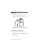
ArmorPOINT RTD and Thermocouple Input Modules Install the Module Follow the instructions to install the ArmorPOINT input module. 1. Using a bladed screwdriver, rotate the keyswitch on the mounting base clockwise until the number 6 aligns with the notch in the base. 2. Position the module vertically above the mounting base. The module bridges two bases. Module bridges two bases. 1738-IR2M12/A RTD (Ohms) In 0 1 MOD NET RTD 0 RTD 1 43782 3.
ArmorPOINT RTD and Thermocouple Input Modules 7 Wire the Module Follow the wiring instructions for the ArmorPOINT input modules.
ArmorPOINT RTD and Thermocouple Input Modules Communicate with the Module I/O messages are sent to (consumed) and received from (produced) the ArmorPOINT I/O modules. These messages are mapped onto the processor’s memory. The ArmorPOINT RTD I/O input module produces 6 Bytes of input data (scanner Rx – status) and fault status data. The ArmorPOINT thermocouple I/O input module produces 8 Bytes of input data (scanner Rx – status) and fault status data. They do not consume I/O data (scanner Tx).
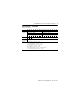
ArmorPOINT RTD and Thermocouple Input Modules 9 Default Data Map – 1738-IT2IM12 Message size: 6 Bytes 15 14 13 12 11 10 09 08 07 06 05 04 03 02 01 00 Produces Input channel 0 high byte (scanner Rx) Input channel 1 high byte Input channel 0 low byte Status byte for channel 1 Status byte for channel 0 Input channel 1 low byte OR UR HHA LLA HA LA OR UR Cold junction temperature (Selectable channel 0, channel 1, or average of both channels 0 and 1) CM CF OR UR HHA LLA HA LA CM CF Consumes N
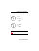
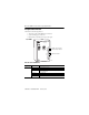
ArmorPOINT RTD and Thermocouple Input Modules Interpret Status Indicators This module has the following indicators: • Adapter, DeviceNet and POINTBus status indicators • System and Adapter power indicators • Individual I/O status indicators for inputs and outputs 1738-IR2M12 1738-IR2M12/A RTD (Ohms) In 0 1 MOD Module status indicator Network status indicator NET RTD 0 I/O status indicator RTD 1 43780 Indicator Status for Modules Module status Status Description Off No power applied t
ArmorPOINT RTD and Thermocouple Input Modules 11 Indicator Status for Modules Status Network status Off Flashing green Description Device is not online: - Device has not completed dup_MAC-id test. - Device not powered – check module status indicator. Device is online but has no connections in the established state. Green Device is online and has connections in the established state. Flashing red One or more I/O connections are in timed-out state.
ArmorPOINT RTD and Thermocouple Input Modules Specifications ArmorPOINT RTD and Thermocouple Input Modules – 1738-IR2M12, 1738-IT2IM12 Attribute Value Inputs per module 1738-IR2M12 – 2 single-ended, nonisolated 1738-IT2IM12 – 2 differential, individually isolated Resolution 1738-IR2M12 – 16 bits, 9.5 mV/cnt, 0.03 °C/cnt (Pt385 @ 25 °) 1738-IT2IM12 – 15 bits plus sign, 2.
ArmorPOINT RTD and Thermocouple Input Modules 13 ArmorPOINT RTD and Thermocouple Input Modules – 1738-IR2M12, 1738-IT2IM12 Attribute Value Input update rate (per module) 1738-IR2M12 40 ms @ Notch = 50 Hz 33 ms @ Notch = 60 Hz (default) 20 ms @ Notch = 100 Hz 17 ms @ Notch = 120 Hz 10 ms @ Notch = 200 Hz 8 ms @ Notch = 240 Hz 7 ms @ Notch = 300 Hz 5 ms @ Notch = 400 Hz 4 ms @ Notch = 480 Hz Step response (per channel) 60 ms @ Notch = 50 Hz 50 ms @ Notch = 60 Hz 30 ms @ Notch = 100 Hz 25 ms @ Notch = 1
ArmorPOINT RTD and Thermocouple Input Modules General Specifications Attribute Value Mounting base screw torque M4 (#8) screw, 0.85 Nm (7.5 lb-in.) in aluminum, 1.8 Nm (16 lb-in.) in steel Calibration Factory-calibrated POINTBus current 1738-IR2 – 220 mA @ 5V DC 1738-IT2I – 175 mA @ 5V DC Power dissipation, max 1.0 W Thermal dissipation, max 3.
ArmorPOINT RTD and Thermocouple Input Modules 15 Environmental Specifications Attribute Value Vibration IEC60068-2-6 (Test Fc, Operating): 5 g @ 10…500 Hz Shock, operating IEC60068-2-27 (Test Ea, Unpackaged Shock): 30 g Shock, nonoperating IEC60068-2-27 (Test Ea, Unpackaged Shock): 50 g Emissions Emissions CSPR 11: Group 1, Class A ESD immunity IEC 61000-4-2: 6 kV contact discharges 8 kV air discharges Radiated RF immunity IEC 61000-4-3: 10V/m with 1 kHz sine-wave 80% AM @ 30 MHz…1000 MHz 10V
Rockwell Automation Support Rockwell Automation provides technical information on the Web to assist you in using its products. At http://www.rockwellautomation.com/support/, you can find technical manuals, a knowledge base of FAQs, technical and application notes, sample code and links to software service packs, and a MySupport feature that you can customize to make the best use of these tools.