Installation Instructions ArmorPoint 4-Channel 24V dc Analog Input Module, Series A Catalog Number 1738-IE4CM12 Topic Page Important User Information 2 Environment and Enclosure 3 Prevent Electrostatic Discharge 3 About the Module 4 Mount the I/O Base 5 Install the Module 6 Remove the Module From the Mounting Base 7 Wire the Module 8 Communicate with Your Module 8 Interpret the Status Indicators 10 Specifications 12
ArmorPoint 4-Channel 24V dc Analog Input Module, Series A Important User Information Solid state equipment has operational characteristics differing from those of electromechanical equipment. Safety Guidelines for the Application, Installation and Maintenance of Solid State Controls (Publication SGI-1.1 available from your local Rockwell Automation sales office or online at http://literature.rockwellautomation.
ArmorPoint 4-Channel 24V dc Analog Input Module, Series A 3 Environment and Enclosure ATTENTION This equipment is intended for use in overvoltage Category II applications (as defined in IEC publication 60664-1), at altitudes up to 2000 meters (6562 ft) without derating. This equipment is considered Group 1, Class A industrial equipment according to IEC/CISPR Publication 11.
ArmorPoint 4-Channel 24V dc Analog Input Module, Series A ATTENTION ATTENTION Make sure all connectors and caps are securely tightened to properly seal the connections against leaks and maintain IP enclosure type requirements. To comply with the CE Low Voltage Directive (LVD), all connected I/O must be powered from a source compliant with the following: Safety Extra Low Voltage (SELV) or Protected Extra Low Voltage (PELV). About the Module The ArmorPoint I/O family consists of modular I/O modules.
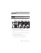
ArmorPoint 4-Channel 24V dc Analog Input Module, Series A 5 Mount the I/O Base Mount the I/O base on a wall or panel, using the screw holes provided in the base. The ArmorPoint I/O module must be mounted on a grounded metal mounting plate or other conductive surface. IMPORTANT Mounting illustration for the ArmorPoint adapter with I/O bases Adapter 46.25 mm (1.8 in) 51.9 mm (2.0 in) 20.1 mm (0.8 in) 51.9 mm (2.0 in) 20.1 mm (0.8 in) 51.9 mm (2.0 in) 56 mm (2.2 in) 102 mm (4.
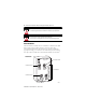
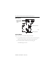
ArmorPoint 4-Channel 24V dc Analog Input Module, Series A Mounting base Set the keyswitch position to 3, for the 1738 analog input modules Ground lug connection 43675 Latching mechanism Install the Module Follow the instructions to install the analog input module. 1. Using a bladed screwdriver, rotate the keyswitch on the mounting base clockwise until the number 3 aligns with the notch in the base. 2. Position the module vertically above the mounting base. The module bridges two bases.
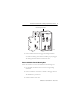
ArmorPoint 4-Channel 24V dc Analog Input Module, Series A 7 Module bridges two bases. 1738-IE4CM12/A Analog Current In 1 0 MOD NET 0 2 3 1 2 3 44368 3. Push the module down until it engages the latching mechanism. You will hear a clicking sound when the module is properly engaged. The locking mechanism locks the module to the base. Remove the Module From the Mounting Base Follow the instructions to remove the module from the mounting base. 1.
ArmorPoint 4-Channel 24V dc Analog Input Module, Series A Wire the Module 1738-IE4CM12 (view into connector) Pin 1 - 24V dc Pin 2 - Input Pin 3 - Common Pin 4 - Common Pin 5 - No Connect 44315 IMPORTANT ATTENTION Analog modules have earth grounded metal rings. This should be considered when choosing shielded cables and grounding techniques. Make sure all connectors and caps are securely tightened to properly seal the connections against leaks and maintain IP enclosure type requirements.
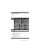
ArmorPoint 4-Channel 24V dc Analog Input Module, Series A 9 Default Data Map for the Module 1738-IE4CM12 Message size: 12 Bytes 15 14 13 12 11 10 09 08 07 06 05 04 03 02 01 00 Produces (Scanner Rx) Input Channel 0 High Byte Input Channel 0 Low Byte Input Channel 1 High Byte Input Channel 1 Low Byte Input Channel 2 High Byte Input Channel 2 Low Byte Input Channel 3 High Byte Input Channel 3 Low Byte Status Byte for Channel 1 Status Byte for Channel 0 O R U R H H A L L A H A L A C C M F Sta
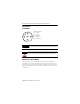
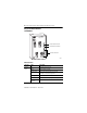
ArmorPoint 4-Channel 24V dc Analog Input Module, Series A Interpret the Status Indicators 1738-IE4CM12 1738-IE4CM12/A Analog Current In 1 0 Module Status Indicator Network Status Indicator MOD NET 0 2 3 1 2 I/O Status Indicators 3 44367 Status Indicators Indicator State Description Module Status Off No power applied to device. Green Device operating normally. Flashing green Device needs commissioning due to missing, incomplete, or incorrect configuration.
ArmorPoint 4-Channel 24V dc Analog Input Module, Series A 11 Status Indicators (Continued) Indicator State Description Network Status Off Device is not on line: - Device has not completed dup_MAC-id test. - Device not powered.Check module status indicator. Flashing green Device is on line but has no connections in the established state. Green Device is on line and has connections in the established state. Flashing red One or more I/O connections in timed-out state.
ArmorPoint 4-Channel 24V dc Analog Input Module, Series A Specifications IMPORTANT Note that the input step response and input update rate for 1738-IE4CM12 differ from those of catalog number 1738-IE2CM12. General Attribute Value Number of inputs 4 Input point density 4 single-ended, non-isolated Input current signal range 4…20 mA 0…20 mA Absolute accuracy(1) 0.1% Full Scale @ 25°C Accuracy drift w/temp.
ArmorPoint 4-Channel 24V dc Analog Input Module, Series A 13 General (Continued) Attribute Value Input step response (per channel) 50 ms @ Notch = 60 Hz (default) 60 ms @ Notch = 50 Hz 30 ms @ Notch = 100 Hz 25 ms @ Notch = 120 Hz 15 ms @ Notch = 200 Hz 12.5 ms @ Notch = 240 Hz 10 ms @ Notch = 300 Hz 7.5 ms @ Notch = 400 Hz 6.
ArmorPoint 4-Channel 24V dc Analog Input Module, Series A General (Continued) Attribute Value Indicators 1 green/red module status indicator, logic side 1 green/red network status indicator, logic side 4 green/red input status indicators, logic side Isolation voltage 50V (continuous), Reinforced Insulation Type, field-side to system Type tested at 1250V ac for 60 s, field-side to system No isolation between individual channels Dimensions (HxWxD), approx. 71.6 x 33.1 x 111.6 mm (2.82 x1.30 x 4.
ArmorPoint 4-Channel 24V dc Analog Input Module, Series A 15 Environmental (Continued) Attribute Value Shock, operating IEC 60068-2-27 (Test Ea, Unpackaged Shock): 30g Shock, nonoperating IEC 60068-2-27 (Test Ea, Unpackaged Shock): 50g Emissions CISPR 11: Group 1, Class A ESD immunity IEC 61000-4-2: 6 kV contact discharges 8 kV air discharges Radiated RF immunity IEC 61000-4-3: 10V/m with 1 kHz sine-wave 80%AM from 80…2000 MHz 10V/m with 200 Hz 50% Pulse 100%AM at 900 MHz 10V/m with 200 Hz 50% Pu
Rockwell Automation Support Rockwell Automation provides technical information on the Web to assist you in using its products. At http://support.rockwellautomation.com, you can find technical manuals, a knowledge base of FAQs, technical and application notes, sample code and links to software service packs, and a MySupport feature that you can customize to make the best use of these tools.