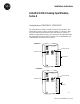
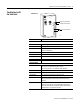
Installation Instructions ArmorPoint 24V dc Analog Input Modules, Series A Catalog Numbers 1738-IE2CM12, 1738-IE2VM12 The ArmorPoint I/O family consists of modular I/O modules. The sealed IP67 housing of these modules requires no enclosure. (Note that environmental requirements other than IP67 may require an additional appropriate housing.) I/O connectors are sealed M12 style. The mounting base ships with the module. The 1738-IE2CM12 and 1738-IE2VM12 modules are shown below.
ArmorPoint 24V dc Analog Input Modules, Series A Important User Information Solid state equipment has operational characteristics differing from those of electromechanical equipment. Safety Guidelines for the Application, Installation and Maintenance of Solid State Controls (Publication SGI-1.1 available from your local Rockwell Automation sales office or online at http://www.literature.rockwellautomation.
ArmorPoint 24V dc Analog Input Modules, Series A ATTENTION 3 Environment and Enclosure This equipment is intended for use in overvoltage Category II applications (as defined in IEC publication 60664-1), at altitudes up to 2000 meters without derating. This equipment is considered Group 1, Class A industrial equipment according to IEC/CISPR Publication 11.
ArmorPoint 24V dc Analog Input Modules, Series A Preventing Electrostatic Discharge ATTENTION This equipment is sensitive to electrostatic discharge, which can cause internal damage and affect normal operation. Follow these guidelines when you handle this equipment: • Touch a grounded object to discharge potential static. • Wear an approved grounding wriststrap. • Do not touch connectors or pins on component boards. • Do not touch circuit components inside the equipment.
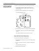
ArmorPoint 24V dc Analog Input Modules, Series A 5 Install the mounting base as follows: 1. Lay out the required points as shown above in the drilling dimension drawing. 2. Drill the necessary holes for #8 (M4) machine or self-tapping screws. 3. Mount the base using #8 (M4) screws. 4. Ground the system using the ground lug connection. The ground lug connection is also a mounting hole.
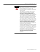
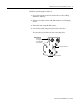
ArmorPoint 24V dc Analog Input Modules, Series A Install the ArmorPoint Analog Input Module To install the ArmorPoint analog input module, proceed as follows. 1. Using a bladed screwdriver, rotate the keyswitch on the mounting base clockwise until the number 3 aligns with the notch in the base. 2. Position the module vertically above the mounting base. The module bridges two bases. Module bridges two bases. 1738-IE2CM12/A Analog Current In 0 1 MOD NET 0 1 43773 3.
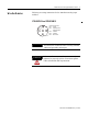
ArmorPoint 24V dc Analog Input Modules, Series A Wire the Modules 7 Following are wiring instructions for the ArmorPoint analog input modules. 1738-IE2CM12 and 1738-IE2VM12 43664 IMPORTANT ATTENTION (view into connector) Pin 1 - 24V dc Pin 2 - Input 0 (M12-A) Input 1 (M12-B) Pin 3 - Common Pin 4 - Common Pin 5 - No Connect Analog modules have earth grounded metal rings. This should be considered when choosing shielded cables and grounding techniques.
ArmorPoint 24V dc Analog Input Modules, Series A Communicate with Your Module I/O messages are sent to (consumed) and received from (produced) the ArmorPoint I/O modules. These messages are mapped into the processor’s memory. These ArmorPoint I/O analog input modules produce 6 bytes of input data (scanner Rx) and fault status data. They do not consume I/O data (scanner Tx).
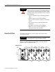
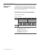
ArmorPoint 24V dc Analog Input Modules, Series A Troubleshoot with the Indicators 9 1738-IE2CM12 1738-IE2CM12/A Analog Current In 0 1 Module Status Indicator Network Status Indicator MOD NET 0 I/O Status Indicators 1 43741 Indication Probable Cause Module Status Off No power applied to device Green Device operating normally Flashing Green Device needs commissioning due to missing, incomplete, or incorrect configuration Flashing Red Recoverable fault Red Unrecoverable fault - may requir
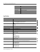
ArmorPoint 24V dc Analog Input Modules, Series A Indication Probable Cause I/O Status Off Module in CAL mode Solid Green Normal (channel scanning inputs) Flashing Green Channel being calibrated Solid Red No power or major channel fault Flashing Red Channel at end of range (over or under) Specifications ArmorPoint Analog Input Modules Number of Inputs Input Point Density Input Voltage Signal Range Input Current Signal Range Absolute Accuracy1 Accuracy Drift w/Temp.
ArmorPoint 24V dc Analog Input Modules, Series A 11 Input Data Format Signed integer General Specifications Calibration Factory calibrated Dimensions, Metric 120H x 72W x 42D Dimensions, Imperial 4.72H x 2.83W x 1.65D External dc Power Supply Voltage, Nom. 24V dc External dc Power Supply Voltage Range 10…28.
ArmorPoint 24V dc Analog Input Modules, Series A General Specifications (cont) Conducted RF Immunity Emissions Enclosure Type Rating Conductor Category2 IEC 61000-4-6: 10Vrms with 1 kHz sine-wave 80% AM from 150 kHz to 80 MHz CSPR 11: Group 1, Class A Meets IP65/66/67 (when marked) 1 - on signal ports c-UL-us UL Listed Industrial Control Equipment, certified for US and Canada CE European Union 89/336/EEC EMC Directive, compliant with: EN 61000-6-4; Industrial Emissions EN 50082-2; Industrial Immunity
ArmorPoint 24V dc Analog Input Modules, Series A 13 Notes: Publication 1738-IN003B-EN-E - June 2005
Rockwell Automation Support Rockwell Automation provides technical information on the web to assist you in using our products. At http://support.rockwellautomation.com, you can find technical manuals, a knowledge base of FAQs, technical and application notes, sample code and links to software service packs, and a MySupport feature that you can customize to make the best use of these tools.